The Short Version
- Tube and pipe use different dimensioning systems. Tube is specified by outside diameter and wall thickness; pipe by nominal size and schedule, where the nominal size is not the outside diameter. The tooling is not interchangeable.
- Two ratios predict bend difficulty. Wall factor compares the diameter to the wall thickness, and D of bend compares the bend radius to the diameter. Both are quick to calculate, and both tell you whether your design is routine or specialized.
- A bend die is specific to a diameter and a radius together. Every distinct combination of the two on your part needs its own die set, which is why standardizing radii across a design saves more than almost any other change.
- Bending stretches and thins the outside of the bend and compresses and thickens the inside. Tighter radii and thinner walls increase both effects, and on pressure-carrying parts the thinned wall is a design condition rather than a cosmetic one.
- Straight length between bends is a manufacturing constraint, not just a dimension. The machine has to grip the tube, and a design that leaves too little material between features may not be bendable as drawn.
- Tolerances on a multi-bend part accumulate, so point-to-point dimensions from a single datum become progressively harder to hold along the part.
- The most useful gauge for a tube assembly is usually a fixture that represents how it fits, rather than a list of coordinates.
Tube fabrication has a particular way of going wrong. The part is drawn by someone thinking about where the fluid needs to go and how the assembly fits together, which is the right way to think about it. Then it reaches a fabricator who explains that two bends share a radius that nobody standardized, one is tighter than the wall thickness supports, and there isn't enough straight length before the third bend for the machine to grip.
None of these are difficult problems if you know them at the design stage. All of them are expensive once the drawing is released and the surrounding assembly is fixed. This guide covers the constraints that determine whether a tube part is straightforward or specialized, in the order they arise, so you can check a design against them before it goes out for quotation.
01. Tube or pipe, and why the distinction matters
These words are used interchangeably in conversation, and they describe two different dimensional systems. Confusing them creates a drawing a fabricator cannot quote without asking, and the answer changes the material, tooling, and price.
Tube is specified by its outside diameter and its wall thickness. A part described as one inch outside diameter with a specified wall is unambiguous: the outside is exactly that dimension, and the wall is what you stated.
A nominal pipe size and a schedule specify a pipe. The schedule determines the wall thickness for that nominal size, and the important point is that the nominal size is not the outside diameter. A pipe carrying an outside diameter of 1.66 inches with a wall of 0.140 inches is called out on a drawing as 1¼ inch schedule 40 pipe, and the relationship between the nominal designation and the actual outside diameter is a matter of published tables rather than arithmetic.
The consequence for fabrication is direct. Bending tooling is sized to actual dimensions, so a die that fits a pipe of a given nominal size is not the die for a tube of a similar-sounding size. If your drawing says pipe, the fabricator will work to the pipe tables. If it says tube, they will work to the dimensions you stated. If it says one and means the other, somebody will notice at a point that costs money.
State which system you are using and give the actual dimensions alongside the designation. It takes one line, and it removes an entire category of misunderstanding.
02. Can the bend actually be made
Two ratios do most of the predictive work, and both can be calculated in seconds from numbers already on your drawing. Running them before you issue an inquiry tells you whether you are asking for routine work or specialized work.
Wall factor
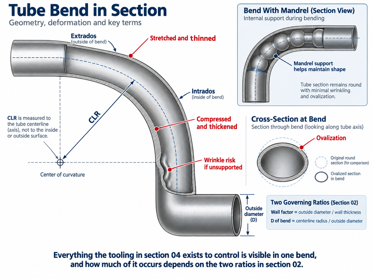
Wall factor is the outside diameter divided by the wall thickness. A thick wall relative to the diameter gives a low wall factor and an easy bend, because there is plenty of material to resist deformation. A thin wall relative to the diameter gives a high wall factor, and thin-walled material is far more likely to wrinkle on the inside of the bend or collapse across the section unless it is supported internally.
As wall factor rises, tooling requirements rise. A modest wall-factor bend uses a basic tool set. A high one usually needs internal support in the form of a mandrel, and a very high one may need a mandrel with multiple articulated balls plus a wiper die, which is more tooling, more setup, and more cost.
D of bend
D of bend describes the bend radius relative to the tube diameter, expressed as a multiple. A bend radius twice the outside diameter is a 2D bend; on a three-inch tube that means a six-inch centerline radius. The higher the D of bend, the easier the bend is to form, because the material is being deformed less severely.
The bend radius itself is normally quoted as the centerline radius, meaning the radius of the arc followed by the axis of the tube rather than by its inside or outside surface. Drawings sometimes give an inside radius instead, which is a different number, so state which convention you are using.
Using the two together
The combination of wall factor and D of bend determines the difficulty of the bend, and the two interact: a tight radius on a thick wall may be straightforward while the same radius on a thin wall is not. As a general orientation, a bend without internal support typically needs a centerline radius of around three times the outside diameter, and tighter radii than that usually require a mandrel.
The practical instruction for a designer is to calculate both figures for every bend on the part and to flag any that sit at the difficult end. Where a bend is marginal, ask the fabricator before finalizing the design, because opening the radius slightly or using a marginally thicker wall can move a specialized bend back into routine territory at negligible cost.
03. Bending methods
Several methods exist, and they suit different combinations of radius, wall, and volume.
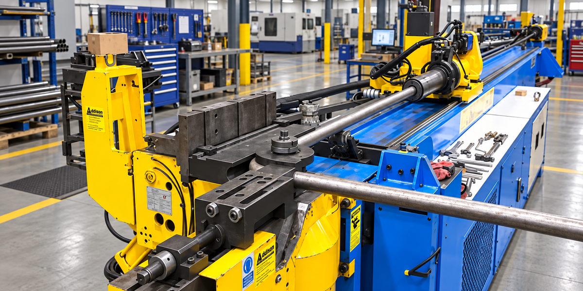
Rotary draw bending is the method most precision tube work uses. The tube is clamped against a rotating bend die and drawn around it, with additional tooling supporting the material through the bend. It produces accurate, repeatable bends, including tight radii; it handles thin walls with the right support, and it is the basis for multi-bend parts produced on a single machine.
Compression bending wraps the tube around a fixed form using a moving shoe. It is simpler and less expensive, and it suits larger radii, typically where the centerline radius exceeds around three times the outside diameter, and simple geometries at higher volumes. It is common in furniture, handrail, and conduit work.
Roll bending passes the tube through three rolls to produce large-radius bends and full curves, which is the usual method for sweeping radii that rotary draw tooling would not economically produce.
Freeform bending moves the tube through a die that shifts position to create a varying radius. Because it does not clamp the tube in the same way, it avoids the marking that clamping can leave, which suits cosmetic and thin-walled work. It is generally less suited to heavy-wall material.
Induction bending heats a narrow band of the tube as it is bent, and it is used for large diameters and heavy walls where cold bending is impractical.
For a buyer, the practical point is not to specify the method but to describe the part and let the fabricator select. A shop quoting rotary draw work and a shop quoting roll bending are quoting different equipment, and if your part could be made either way, it is worth asking both.
04. Tooling, and why it multiplies
This is the cost driver buyers most often miss, and it's why two apparently similar parts can be priced very differently.
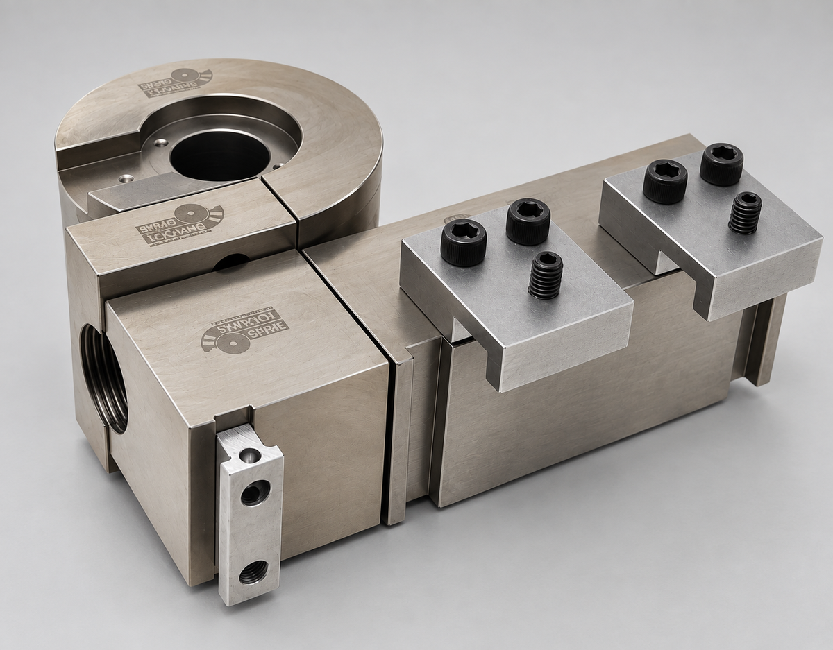
In rotary draw bending, the essential tools are the bend die, which forms the radius, the clamp die, which holds the tube against it, and the pressure die, which supports the tube as it is drawn. Depending on wall thickness and radius tightness, you may need a mandrel inside the tube to hold the section round, and a wiper die behind the bend to prevent wrinkling on the inside. Parts with several bends also require a mechanism that grips the tube and rotates and positions it between bends.
The critical point is that a bend die is specific to both diameter and radius. It is not a diameter tool that works at any radius, and it is not a radius tool that works at any diameter. Each distinct combination of outside diameter and centerline radius on your part requires its own die set. If your design uses three diameters across four radii, that is potentially twelve combinations rather than seven tools.
Two design decisions follow directly, and both are free at the drawing stage.
Standardize the bend radius across the part and across the part family wherever the design allows. Using one radius throughout means one bend die, and it is the single most effective way to reduce tooling cost in this category.
Then ask the fabricator which radii they already hold tooling for at your diameter. Shops accumulate tooling over years, and if one of their existing radii works for your design, that tooling cost disappears entirely. Designers rarely ask this because it feels like letting the supplier dictate the design, and on a non-critical radius it is simply free money.
Establish also who owns any tooling purchased for your part, where it is stored, and what happens if you move the work. The same questions apply here as to any dedicated tooling, and they are easier to settle at the order than later.
05. What the bend does to the tube
Bending is a forming operation, and it changes the material, which matters for parts that carry pressure, seal at their ends, or fit into tight assemblies.
At the outside of the bend, the material is stretched, so the wall thins. At the inside, it is compressed, so the wall thickens and, if unsupported, wrinkles. The section also tends to flatten into an oval rather than staying round. All three effects increase as the radius tightens and as the wall gets thinner relative to the diameter, which is why the two ratios in section 02 predict them.
Three consequences are worth designing around.
If the tube carries pressure, the thinned wall on the outside of the bend governs the thickness rather than the wall you ordered. When that matters, calculate it rather than assume it, and start with a heavier wall so the thinned section still meets the requirement. Specify the minimum acceptable wall after bending, not the starting wall, and let the fabricator work back from it. On a part governed by a pressure piping code, this is not a matter of good practice but of the code's own bending provisions, which require the finished bend to meet a minimum thickness. The applicable code follows from the application, as set out in section 02, and the calculation belongs to your engineering function, not the fabricator. If nobody on your side has done it, that is the work to do before the inquiry rather than after the first article.
If the tube has to seal or fit closely at or near a bend, ovality matters. State the permitted ovality, which some fabricators will call out-of-roundness and which means the same thing: the difference between the largest and smallest diameters across the section at the bend, if it is important, and be aware that holding a tight ovality on a tight radius requires mandrel support and therefore tooling and cost.
And springback means the tube relaxes slightly after the bending force is released, so fabricators overbend to compensate. The amount depends on the material, its condition, and the geometry, which is why a first article on a new part tells you things a calculation does not.
Straight length between bends
This constraint is most often missed at the design stage. The machine has to grip the tube to bend it, which requires a length of straight material adjacent to each bend for the clamp to hold. If two bends are placed too close together, or a bend is too close to an end feature, the part may not be manufacturable as drawn even though nothing about it looks unreasonable on paper.
The minimum depends on the machine, the tooling, and the diameter, so it is a question for the fabricator rather than a universal number. Ask early, before the surrounding assembly fixes the geometry, because a bend that has to move by a small amount is a trivial change at design stage and an expensive one afterward.
06. End forming
Most fabricated tube parts need something done to their ends beyond cutting, and the end forms are worth knowing by name so a drawing can call for them precisely.
Expansion increases the end diameter so another tube fits inside, and reduction decreases it so the end fits into something else. Flaring opens the end into a cone, usually to seat against a fitting. Beading forms a raised ring near the end so a hose clamped over it cannot pull off. Grooving forms a channel to receive a seal or a retaining ring. Swaging tapers or steps the end down. Flattening presses the end flat, often to receive a fastener. Notching cuts the end to a profile so that one tube seats against the curved surface of another, which is what makes welded tube joints fit.
Two things determine whether an end form is straightforward. The first is how far the material has to move, since a large expansion or reduction is a significant forming operation and may need several stages. The second is the material's workability, since a hard or heavily worked material will crack where a softer one would form cleanly.
End forming is a separate tooling question from bending, and the tooling depends on the diameter and the form. So the same standardization argument applies: a design using two end forms across one diameter is cheaper than one using four across three.
Finally, establish how the end form interacts with the bend nearest to it. An end form needs a length of straight tube to hold and to work, exactly as a bend does, so an end form close to a bend has the same constraint discussed above.
07. Tolerances and how tube parts are actually gauged
Tube fabrication tolerancing behaves like other forming processes: individual features can be held closely, but their accumulated relationships cannot, because each bend adds its own small variation in angle, rotation, and position along the tube.
The practical consequence is that a long multi-bend part dimensioned point to point from a single datum becomes progressively harder to hold along its length, and a drawing that applies the same tight tolerance to every dimension has specified something both expensive and, past a certain point, not achievable.
The remedy is the same as in sheet metal and wire forms. Identify the few features that actually matter, which are usually the ends and any point where the part is clamped or connected, tolerance those closely, and let the intermediate geometry carry a general tolerance.
Gauge it the way it fits
The more useful principle is to check a tube assembly against a fixture that represents how it installs, rather than against a list of coordinates. A part can meet every dimension on a coordinate measuring report and still not fit, because the dimensions were measured from a datum the assembly does not share.
A checking fixture holds the part at the points where the real assembly holds it and shows immediately whether the free ends land where they need to. It is tooling with a cost, and on a part that matters it usually pays for itself at the first production run by ending the argument about whether an out-of-tolerance dimension is actually a problem.
Where a fixture is not justified, tube measuring systems that determine bend geometry and compare it to the model are common in this sector, and they produce correction data the bending machine can use directly. Ask what the fabricator uses and what the report will look like, because a report you cannot interpret is not a quality record.
What to specify
State the tolerance on overall length and on the critical end positions. State the tolerance on bend angle and on the rotation between planes if the part is three-dimensional. State the permitted ovality and the minimum wall after bending if either matters. State how the part will be checked and against what, and if you intend to gauge it in a fixture, say so, because the fabricator will build to that.
08. Material, welds and finishing
Material is not a detail to settle after the geometry. On any part governed by a code, it determines what is permitted, and in every case it determines which fabricators can work it and how the part behaves during forming. Section 02 treats it as a shortlist filter, which it is; this section covers what must appear in the specification.
State the material specification, not just the alloy family, and state the condition or temper, because formability depends on it. Specifying only the alloy leaves the fabricator choosing, and that choice affects whether a marginal bend succeeds.
If the tube is welded rather than seamless, the weld seam is a real feature. Buyers will meet three descriptions in supplier catalogs. Seamless tube is formed without a longitudinal weld. Electric resistance welded tube, usually abbreviated ERW, is formed from strip and welded along its length. Drawn over mandrel tube, abbreviated DOM, starts as welded tube and is then cold drawn over a mandrel, which improves dimensional accuracy and surface finish and works the weld area. It runs the length of the tube; it behaves slightly differently from the parent material during forming, and on some parts its position matters, either because it must be positioned away from a tight bend or because it must be oriented consistently for appearance or for a downstream operation. If seam position matters, say so; otherwise, it lands wherever the material happened to be loaded.
For fluid-carrying parts, establish the internal cleanliness requirement. Bending, end forming, and cutting generate debris, and whether the part needs washing, must be capped after cleaning, and what cleanliness standard applies are specification items, not assumptions.
Also establish whether the part is welded into an assembly, since fixture requirements, weld process, and any post-weld treatment become part of the same purchase. Also establish the required finishing: deburring, end facing, surface finish, plating, painting, or passivation, and whether dimensions apply before or after any coating.
09. What to send a fabricator
A fabricator quoting from a length and a bend count is guessing at most of what determines cost. The package below lets you quote a specific part and compare several quotations.
The part
A three-dimensional model, which for tube work is worth more than a drawing because bend geometry is difficult to convey in two dimensions. Alongside it, a drawing carrying the tolerances, critical features, and anything the model cannot express. And the bend data, if you have it: the sequence of straight lengths, bend angles, bend radii, and rotations that defines the part, which is the form a bending machine actually works in.
The specification
Whether the material is tube or pipe, with the designation and the actual dimensions. The material specification and condition. The wall thickness, and separately the minimum acceptable wall after bending if the part carries pressure. Bend radii, stated as centerline radii and standardized wherever possible. Permitted ovality if it matters. Weld seam orientation if it matters.
The requirements
End forms, by name and with their dimensions. Tolerances on overall length, on critical end positions, on bend angles and on rotations. Internal cleanliness requirements. Finishing and whether dimensions apply before or after it. How the part will be inspected and against what, including whether a checking fixture is required and who provides it.
The commercial
Quantities now and annually, and the release pattern. Whether this is a prototype, a bridge quantity, or production, since those are different conversations. Which bend radii the fabricator already holds tooling for, asked as a question rather than stated as a requirement. And whether the design is open to change, because a fabricator invited to comment will usually identify one or two adjustments that reduce tooling or difficulty at no functional cost.
One further note on how to ask. A fabricator who responds by asking about your wall factor at the tightest bend, the straight length before the third bend, and whether the radii can be standardized is engineering your part. One who returns a price against a length and a bend count has quoted a shape, and the difference between those responses usually appears at first article.
Take This to Your Next Conversation
Fifteen questions drawn from this guide.
- Which bends on this part are you treating as difficult, and why?
- What is the wall factor and D of bend at my tightest radius, and does that need a mandrel?
- Which bend radii do you already hold tooling for at my diameter?
- If I standardized all the radii on this part to one value, what would that save?
- Is there enough straight length between my bends and before my end forms for your machine to grip?
- What wall thickness should I start with so the thinned section still meets my minimum after bending?
- What ovality should I expect at the tightest bend, and what would holding it tighter cost?
- Does the weld seam position matter on this part, and can you control it?
- What tooling would this part need, what would it cost, and who would own it?
- How will you inspect this, and would a checking fixture be worth building?
- Will you gauge it based on how it fits in my assembly, or from a coordinate datum?
- What internal cleanliness can you deliver, and how will you protect the part after cleaning?
- How many bends can you produce in one setup, and does my part require more than one?
- What would you change about this design to make it easier, without affecting function?
- What have you seen go wrong on parts like this, and what changed as a result?
About this guide
Written by the Industrial Web Search editorial team. This guidance is general and does not replace engineering advice for a specific part. Achievable bend radii, wall thinning, ovality, and tolerances depend on the material, its condition, the geometry, the tooling, and the equipment, and the general orientations given here should be confirmed against a fabricator's capability for your specific design. Where a tube or pipe carries pressure or serves a safety function, the applicable design code governs, and you should calculate wall thickness after forming rather than assume it. Material specifications, dimensional standards, and code requirements vary by application and by market, and their current editions are the authority. Confirm design, material, and code requirements with a qualified engineer for your application.