
The Short Version
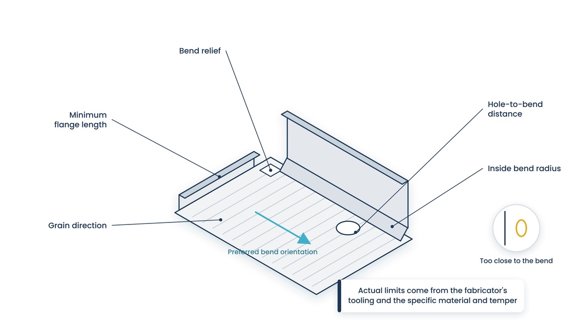
- Every published sheet metal design rule is a rule of thumb, and the published figures disagree with each other because the real limits come from the fabricator's tooling and the specific alloy and temper. Ask for their design guidelines rather than applying someone else's.
- Grain direction matters. Bending parallel to the grain increases the risk of cracking on the outside of the bend, particularly in aluminum, but this constraint is not captured in the model.
- Tolerance accumulates across bends. A dimension that spans several forming operations cannot hold the same tolerance as one within a single flat face, and specifying otherwise is the most common cause of a part being quoted expensively or rejected on receipt.
- The order of operations is part of the specification. Whether hardware goes in before or after finishing, and whether dimensions apply before or after coating, changes what the fabricator has to do and what arrives.
- Cost is driven more by setup, by how many parts nest on a sheet, and by how many separate operations the part requires than by the amount of metal in the finished part.
- A fabricator who returns design feedback during the quoting period is doing the most valuable thing available to you, and it is worth inviting explicitly rather than hoping for it.
Preparing a sheet metal RFQ looks like preparing any other fabrication inquiry. Send drawings, state a quantity, ask for a price. The reason it needs its own treatment is that sheet metal parts are made by cutting a flat blank and then forming it, and the flat blank is not something you can derive from the finished dimensions without knowing how that particular shop bends metal.
That single fact produces most of the difficulty in this category. It explains why the same model quoted at three shops can come back with three different flat patterns, why a tolerance that seems reasonable on the drawing can be impossible after four bends, why a hole placed too close to a bend line arrives as an oval, and why a part designed without reference to any fabricator's tooling can be quoted at a price nobody expected. This guide walks through the sequence from the first decision to reading the quotes, and the order matters because each step closes questions that the next one depends on.
01. Why sheet metal RFQs go wrong
Four failure patterns account for most of the trouble, and all of them originate in the request.
- Design rules are applied from a general source. Published minimum flange lengths, hole-to-bend distances and bend radii vary considerably between sources, because the true values depend on tooling and material. A part designed to one source's numbers may be unmanufacturable at the shop quoting it.
- Tolerances are applied uniformly across a formed part. Forming accumulates variation, so a tolerance that is routine within one flat face becomes expensive or impossible across three bends.
- The order of operations is unstated. Whether hardware is installed before or after finishing, and whether dimensions apply before or after coating, both affect the part and are frequently left to the shop to guess.
- The quantity picture is incomplete. Sheet metal economics turn on setup and nesting, so a quantity quoted without the annual usage or the release pattern produces a number that does not describe the program.
02. Decide before you send anything
Five questions have to be answered internally first. A fabricator cannot resolve them.
- What does the part do, and what does it mate with? Which faces and features are functional and which are simply enclosure?
- What material is genuinely required, and is there latitude? Alloy and temper affect formability as much as strength.
- What finish is required, and is it cosmetic, protective, or both? Cosmetic requirements need to be treated separately from functional ones.
- Does the part need to be welded, and if so, is the weld structural or merely joining?
- What inspections and documentation do you require upon delivery, and does first-article approval apply?
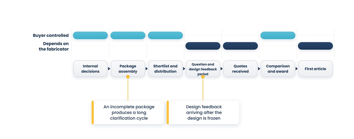
One further question is worth adding before an inquiry goes out on a new design: are you willing to change the part? A fabricator reviewing a design against their own tooling can frequently identify changes that reduce cost substantially without affecting function, but only if the design is still open. Saying so in the inquiry changes the quality of what comes back.
03. Geometry: send the model, not the flat pattern
First, establish which kind of RFQ this is
The advice in this section is written for a new part where the design is still open. That is the most common case and not the only one, and the three differ in who owns the manufacturing geometry.
- Design intent. The finished part is defined, and the manufacturing geometry is not. Send the model and the drawing, let the fabricator develop the flat pattern, and invite comment on the design. Everything below applies.
- Build to print against a released configuration. A controlled document defines the part and may include a released flat pattern. Identify the governing document and its revision, state whether the supplier may alter the manufacturing geometry at all, and if so require it to go through an approved deviation or engineering change rather than being adjusted quietly. Do not hand development to the fabricator here; you would be giving up configuration control.
- Transfer of an existing part. Someone has made this before. Send the first article history, the inspection results, any known bend deductions or controlled flat pattern, the critical interfaces, and a sample part if one exists. A new supplier reproducing a part from a model alone will reproduce it to their own geometry, which is a different part from the one currently in your assembly.
Why the flat pattern belongs to the fabricator
When sheet metal is bent, the material on the outside of the bend stretches, and the material on the inside compresses, with a neutral plane somewhere in between that neither stretches nor compresses. The position of that plane, expressed as a proportion of the material thickness, determines how much material the bend consumes and therefore how large the flat blank must be. That position is not a universal constant. It shifts with material, temper, thickness, inside radius, bending method, and press tooling.
A fabricator determines it from their own measured results on their own equipment. A flat pattern developed in your CAD system uses whatever value that system defaults to, and the two will rarely agree. Sending your flat pattern, therefore, either forces the fabricator to discard it or produces parts sized against your assumption rather than their process.
Send a 3D model of the finished part. Send a 2D drawing alongside it that states the requirement: which dimensions are critical, what tolerance applies to each, the datum scheme, finish, hardware, and any notes. State explicitly which document governs if the two disagree. If you have a flat pattern, you can supply it for reference, but label it as reference only and say the fabricator should develop their own.
File formats
STEP is the standard neutral 3D exchange format and is what most fabricators ask for. A flat DXF is useful for a laser-cut-only part with no forming, and misleading for a formed part unless clearly marked as reference. Always include a 2D drawing as a PDF, because it is the file everyone can open and the one that ends up at the machine and the inspection bench.
What the drawing must carry
- Bend lines and bend directions, unambiguously. Nearly symmetric parts are a known hazard, because the operator can form them backward. Where a part is almost symmetric, either make it symmetric or make the orientation obvious.
- Which dimensions are critical, and which are reference. On a formed part, this distinction carries more weight than on a machined one, because it tells the fabricator where to place the accumulated variation.
- Inside bend radius, or a note that the fabricator should apply their standard radius for the material and thickness. The second is usually the better answer, since it lets them use tooling they already have.
- Hardware locations, part numbers, orientation, and the side from which they install.
- Weld locations and types using standard symbols, with a statement of whether welds are structural.
- Finish, including which surfaces are cosmetic and which areas must be masked.
04. Material, gauge and grain
Specify all four attributes
A material callout needs the alloy or grade, the temper or condition, the thickness, and the surface or coating condition. A family name is not a specification, and in sheet metal the temper matters unusually much because it governs formability. Two aluminum alloys of the same thickness can behave completely differently in a bend, and a temper chosen for strength may require a much larger bend radius than a more formable one, thereby changing the geometry of the part.
Thickness deserves care. Gauge numbers are not consistent between materials, so a gauge number without a decimal equivalent and a material is ambiguous. Mill tolerance on thickness is also real, and where a part must fit into a tight assembly, that variation is part of the tolerance stack whether or not it was accounted for.
Where you have latitude on material, say so. A fabricator holding a common alloy in stock in your thickness may quote materially better than one who has to order in, and they cannot offer that if the specification appears fixed.
Grain direction
Rolled sheet has a grain direction, and bending parallel to that grain raises the risk of cracking on the outside surface of the bend. The effect is most pronounced in aluminum and in harder tempers. Bending across the grain is generally preferred where the geometry allows it.
This matters to an RFQ for two reasons. It is a constraint the 3D model cannot express, so if grain orientation is critical to your part, it has to be called out on the drawing. And it interacts with nesting, because forcing a grain orientation restricts how parts can be laid out on the sheet and can reduce material yield, which shows up in the price. If the orientation is not critical, saying so is worth money.

05. Forming: the constraints that come from tooling
The published rules disagree, and that is the point
Search for sheet metal design rules, and you will find minimum flange lengths given as a multiple of thickness that varies by source, hole-to-bend distances expressed several different ways, and minimum bend radii quoted differently for the same material. The disagreement is not carelessness. These figures are approximations of a physical situation that depends on the press brake, the punch and die set in it, the die opening, the material, the temper and the thickness.
The practical consequence is to stop treating any published figure as authoritative and to ask each fabricator for their own design guidelines before finalizing a design. A design built to a generic web source may be unmanufacturable at the shop that ends up quoting it. Note the limit of that principle: a fabricator's guidelines govern what their tooling can make, not what your drawing requires. Where their capability conflicts with a released design, a contractual requirement or a regulatory one, that is a deviation to be raised and agreed, not a substitution to be made quietly.
The constraints worth understanding
- Minimum flange length. A flange has to be long enough for the tooling to grip and form it, and the limit follows from the die opening rather than from the material alone. A flange shorter than the tooling permits cannot be formed at all, which turns a small design detail into a redesign.
- Distance from a hole or slot to a bend line. Material moves during forming, so a feature too close to the bend is affected: it can elongate, deform, shift out of position, or mark, and how much depends on thickness, radius, method and how close it sits. The safe distance depends on thickness and bend radius together.
- Bend relief. Where a bend terminates next to adjacent geometry, small cutouts relieve the stress that would otherwise tear the material. Omitting relief can make a part unmanufacturable rather than merely imperfect.
- Inside bend radius. A radius too small for the material and temper cracks the outside of the bend. Larger radii are safer, and using the fabricator's standard tooling radius is usually both cheaper and more reliable than specifying an unusual one.
- Springback. Metal partly returns toward flat after the punch retracts, and the press compensates by overbending. The amount depends on material and thickness, which is one more reason the fabricator's own data governs.
- Bend sequence and tool access. Each bend has to be formed with the already-formed part clearing the machine. A part that is geometrically valid can still be impossible to form in any order, and this is exactly the kind of problem a fabricator catches during quoting if you invite them to.
- Consistent bend direction. Parts requiring the operator to flip between bends cost more, and every handling step is an opportunity for error.
06. Hardware, welding and finish
Order of operations is a specification
A sheet metal part usually passes through several processes: cutting, forming, hardware insertion, welding, and finishing. The order changes the result, and it should be stated rather than left to the shop.
The most common example is hardware and finish. Self-clinching fasteners installed before painting will be coated, which can affect thread fit and electrical continuity. Installed after painting, the insertion can damage the finish around them. Neither is universally right, and which one you want depends on whether thread condition or cosmetic finish matters more. Say which.
The same applies to dimensions. State whether dimensions apply before or after finish, because coatings add thickness. On close-fitting features and on holes that must accept hardware, that thickness is the difference between a part that assembles and one that does not.
Welding
- Use standard weld symbols and state whether welds are structural or cosmetic. The two carry different inspection and different cost.
- Name the welding standard the work is to be performed and qualified to, appropriate to the base material, and state any welder or procedure qualification requirement.
- Address distortion. Welding sheet metal puts heat into thin material, and distortion is a normal consequence rather than a defect. Where flatness or dimensional accuracy after welding is critical, say so, because the fabricator may need to fixture, sequence, or straighten, and that is work to be priced.
- State the required weld finish, since ground flush, blended, and as-welded are very different amounts of labor.
Finishing
- Name the finish specification, not just the process. Powder coat, wet paint, anodize, plating, and passivation all have their own governing specifications, including types, classes, and thicknesses.
- Specify color and gloss where they matter, and state whether a color match is required against a sample.
- Identify masking requirements: threads, ground points, bearing surfaces, mating faces, and any area that must remain conductive.
- State cosmetic expectations for visible surfaces separately from functional finish, including what level of surface imperfection is acceptable.
- Say whether the finish is applied in-house or subcontracted, and whether that affects lead time, because outside finishing is a separate schedule running inside the fabricator's.
07. Tolerance, quantity and what drives cost
Tolerance on a formed part
Tolerance in sheet metal behaves differently from tolerance in machining, and this is the point most often missed by buyers who are fluent in machined parts. A machined feature is cut to size in one setup. A formed feature's position depends on the accuracy of the blank, the accuracy of every bend before it, and the angular accuracy of each of those bends, and those variations accumulate.
Three consequences follow. A dimension within a single flat face can hold a tighter tolerance than one spanning several bends. Angular tolerance on a bend is a separate specification from linear tolerance and should be stated. And applying one tight tolerance block to a whole formed part either raises the price substantially or produces parts that fail inspection, sometimes both.
The discipline is the same as in machining, but the geometry is different: identify the few dimensions that actually matter to function, tolerance those, and let everything else fall to a general block. On a formed part, it also helps to consistently nominate a datum face and dimension from it, so the fabricator knows where you want the accumulated variation to end up.
Free state and assembled state
A formed part can meet every dimension on the drawing and still fail in the assembly. This is the failure that shows up after first articles are approved: nothing is out of tolerance, and the enclosure does not sit square, the connector does not line up, or the door gaps unevenly. Six questions prevent it, and all six belong in the drawing rather than in a conversation later.
- Which dimensions are critical in the assembled state rather than free, and what fixture or mating part establishes that state for inspection?
- Whether flatness and profile requirements apply before or after welding, finishing, and hardware insertion, since all three move the part.
- Whether the part is measured free, clamped, or on a functional fixture. A part that passes clamped and fails free is a different part from one that does the reverse, and the drawing has to say which applies.
- Whether positional tolerances run from a datum scheme that survives forming, or from edges that accumulate bend variation. The second looks controlled on the drawing and is not.
- Which holes have to align across the assembly and which can use clearance, slots, or floating hardware instead. Every hole that does not need a true position is cost-removed.
- Whether the design assumes a nominal inside bend radius while the assembly depends on an exact outside dimension. That outside dimension varies with the actual tooling and the material lot, and this mismatch is a common, quiet source of assembly problems.
What drives cost
- Setup rather than material. Programming, tool changes at the press brake, and fixture preparation are largely fixed per run, which is why unit price falls steeply with quantity and why a small quantity of a complex part can look surprisingly expensive.
- Nesting yield. Parts are laid out on standard sheets, and the price reflects how much of the sheet is used. A small change to a part outline can improve how many fit per sheet, which is the kind of saving a fabricator can identify if the design is open.
- Number of operations. Each distinct process the part passes through adds handling, queue time, and cost, so consolidating operations usually beats optimizing any one of them.
- Tolerance and cosmetic requirements, which raise inspection and scrap rates rather than machine time.
Quantity
State the quantity to be quoted, the expected annual usage and the release pattern, and ask for price breaks at defined quantities. Because setup dominates, the breakpoints tell you where the economics of your program actually lie, and that is useful information for your own planning, regardless of what you order first.
08. Issuing the RFQ and running the question period
Build the shortlist first
Shortlist on capability rather than broadcasting. What matters here is the equipment: cutting method and bed size, press brake capacity and tooling range, whether welding and finishing are in-house or subcontracted, and whether the shop routinely works with your material, thickness, and volume band. A shop that is capable but works at a different scale will either decline or quote defensively.
Invite design feedback explicitly
This is the single practice that separates a good sheet metal RFQ from an adequate one. Say in the inquiry that the design is open to manufacturability feedback, and ask each bidder to identify changes that would reduce cost without affecting function. Fabricators see these opportunities constantly and usually stay silent, because volunteering changes to a customer's drawing is presumptuous unless invited.
The feedback also tells you something about the bidder. A shop that returns two or three specific, well-reasoned suggestions has engineered your part. A shop that returns only a price has run it through a quoting system.
Run the question period deliberately
Set a date for questions and a date for answers, and circulate every question and every answer to every bidder rather than only to the one who asked. A question one shop asks reveals an ambiguity all of them are dealing with, and answering privately means the bidders are quoting against different information. This does more for comparability than anything else in the process.
If something changes
Revise the document, increment the revision, reissue to everyone, and extend the deadline. Verbal changes and one-to-one corrections destroy comparability and leave a record nobody can reconstruct when a part arrives wrong.
09. What comes back, and how to read it
What turns a quote into a program
Everything above gets you a comparable price. The requirements below determine whether the first order can become a repeatable production order, and they belong in the RFQ rather than being settled after award.
- Configuration control. Part number, revision, and which document governs if the model and drawing disagree. State the route for discrepancies, deviations, and engineering changes, and who has authority to approve one.
- First article. Quantity, report format, whether a ballooned drawing is required, who approves it, whether sample retention is required, and whether production may begin before approval. This is program control, not an inspection preference, and leaving it vague is how a first article becomes a dispute.
- Inspection basis for the formed dimensions that matter, tied to the free state and assembled state questions in section 07.
- Material traceability: mill test reports, certificate of conformance, lot traceability, any domestic sourcing requirement, and whether substitution is permitted at all.
- Finish verification: thickness, adhesion, color and gloss tolerance, corrosion testing where required, and whether a cosmetic acceptance sample governs.
- Hardware and weld acceptance: approved hardware manufacturer and part number, weld procedure and qualification, visual acceptance criteria, and distortion limits after welding.
- Packaging, protective film, labeling, part orientation, lot segregation and delivery documentation.
What a complete quote contains
- Unit price at the quantity requested and at any break quantities.
- One-time costs stated separately: programming, tooling, fixtures, and any first article charge.
- Lead time for the first delivery and for repeat orders, since the first run carries setup that later runs do not.
- The material specification and thickness quoted, in the fabricator's own words, which is how you check they read your requirement as you wrote it.
- Which operations are in-house and which are subcontracted, with outside process lead times identified.
- Any exceptions, assumptions or clarifications the fabricator is taking to your package.
- Quote validity period.
Read the exceptions and the feedback first
A quote that lists assumptions is more useful than one that does not. A fabricator noting that they have assumed a particular bend radius, or that they will develop their own flat pattern, or that a stated tolerance cannot be held across a given span, is giving you engineering information at no cost. Read that before the price, because it frequently changes what the price means.
Warning signs
- A single number with no breakdown, which cannot be compared and hides where the cost sits.
- Acceptance of a tolerance across multiple bends that other bidders queried. Either they have a capability the others lack, which is worth understanding, or they have not read it.
- Lead time given as a range with no commitment, or omitted.
- Reluctance to identify which operations are subcontracted.
Comparing
Normalize before comparing. Put every quote on the same basis: total cost at the quantity you will actually buy, one-time costs amortized over that quantity, freight included, against a common delivery date. Then note where bidders took different exceptions, because a lower price achieved by assuming a looser tolerance or a larger bend radius is not a lower price for the same part.
Take This to Your Next Conversation
Fifteen questions drawn from this guide. The first several are for the fabricator, the last few for your own team before the package goes out.
- Will you develop your own flat pattern, and what did you assume for material behavior at the bends?
- Can you send me your design guidelines for minimum flange length, hole-to-bend distance, and bend radius in this material and thickness?
- Which features in this part drove your price, and which could be relaxed without affecting its functionality?
- What inside bend radius did you quote, and is it standard tooling for you?
- Can this part be formed in a workable bend sequence, or does any bend interfere with earlier ones?
- Is grain direction constrained in your nesting, and would releasing that constraint improve the price?
- Do the drawing dimensions apply before or after finish, and how did you interpret that?
- Is hardware installed before or after finishing in your process, and what does that mean for my threads and my cosmetic surfaces?
- What tolerance can you actually hold across the dimensions that span several bends?
- What would you change about this part to make it cheaper without changing what it does?
- Before issuing: have we sent the model rather than a flat pattern, and said which document governs?
- Before issuing: have we identified the few dimensions that matter and let the rest fall to a general block?
- Before issuing: have we said the design is open to manufacturability feedback?
- Which of my dimensions did you read as critical in the assembled state, and how would you inspect those: free, clamped, or on a fixture?
- What are your first article requirements, who approves it, and may production start before approval?
About this guide
Written by the Industrial Web Search editorial team. This guidance is general and does not replace engineering advice for a specific part or program. Design rules for forming are approximations that depend on tooling, material and temper, and the fabricator's own published guidelines take precedence over any general figure. Drafting, welding, finishing, and inspection standards are revised periodically, and their current editions are the authority, which is why the practice recommended throughout is to name both the standard and the edition on the drawing. Verify every specification against the current edition of the governing standard, and confirm manufacturability with the fabricator before a design is frozen.