The Short Version
- A service factor corrects a nominal rating for the character of the application: how the driven machine loads the drive, how many hours a day it runs, and how much shock it delivers. It is a correction for known conditions, not a safety margin, and treating it as one leads to stacking factors and oversizing.
- A bearing life rating is a statistical figure at a stated reliability under stated conditions. The basic figure is the life expectancy that 90% of a group would reach, which means it is neither a minimum nor a prediction for your specific bearing.
- Life rating standards explicitly exclude some of the things that actually kill bearings in service, including wear, corrosion, and electrical erosion. A calculation showing a long life says nothing about those failure modes.
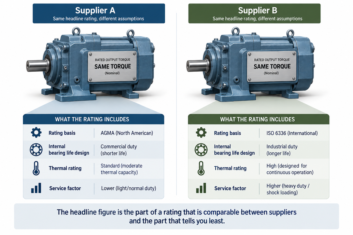
- Gear ratings come from multiple systems and are not equivalent. The same physical gearset, rated under different systems, yields different published capacities, so two catalog entries showing the same torque are not necessarily comparable.
- A gearbox has both a mechanical rating and a thermal rating, and the lower of the two governs. The thermal rating is often the lower one, so a unit that is mechanically capable of your torque can still be unable to shed the heat your duty produces.
- Couplings do three different jobs: transmit torque, accommodate misalignment, and in some designs protect the machine or tune the torsional behavior. Establish which of those you are buying.
- Alignment, mounting, and lubrication determine whether components reach their rated life. Most premature failures in this category are installation and lubrication failures rather than selection failures.
Bearings, gears, and couplings are bought against numbers, and the numbers are unusually easy to misread. A bearing life figure looks like a prediction and is a statistical statement about a population. A gear torque rating looks like a physical capacity and is partly a function of the rating system used. A service factor looks like a margin and is actually a correction for conditions the base rating did not assume. Each of these is well understood by the engineers who produce them and routinely misunderstood by the people who compare them.
The three families also share a set of variables, which is why they belong in one guide: the load and how it arrives, the hours and duty, the environment, and the alignment and lubrication that determine whether the calculated life is ever achieved. This guide covers the common variables first, then takes each family in turn to show where the same principles apply differently, and closes with the rating-system question that makes catalog comparison harder than it looks.
01. Start from the driven machine, not the component
Ten facts define the requirement, and most of them describe the machine rather than the part being bought.
- What is being driven and what it does to the drivetrain. A centrifugal fan, a reciprocating compressor, a crusher, and a conveyor start and load in completely different ways.
- Power and speed at the component in question, with the direction of power flow clear.
- How load arrives: steady, fluctuating, shock, or reversing, and how often. Shock and reversal are the service factors that service factors principally correct for.
- Starting conditions: whether the drive starts under load, how often it starts, and the starting torque and inrush involved.
- Hours of operation per day and days per year, since duty hours directly affect service factor selection.
- Load direction and magnitude on the component: radial, axial, moment, and combinations, including loads from belt tension, overhung weight, thermal growth, and piping or structural reactions.
- Required life as several hours or cycles rather than as an expectation, and what happens when it is reached.
- Environment: temperature range, contamination, moisture, wash-down, chemical exposure, and accessibility for maintenance.
- The mounting arrangement, shaft and housing dimensions and tolerances, and the method for installing and removing the component.
- What has to happen on overload depends on whether the coupling protects the machine or the machine protects the coupling; that decision should be made deliberately.
Two of these are worth emphasizing. Start conditions frequently produce the highest loads the drivetrain ever sees, and they are the ones a steady-state calculation misses. And the required life, stated as a number, is what makes competing proposals comparable; without it, a supplier will assume one.
02. The service factor, and what it is not
What it corrects for
A service factor is a multiplier applied to the nominal load or torque to arrive at the load a component should be selected against. It exists because catalog ratings are established under defined, comparatively benign conditions, and real applications differ from those conditions in ways that are known and quantifiable: the driven machine may deliver shock, the drive may run continuously rather than intermittently, it may start many times a day, or the load may reverse.
Published service factor tables are organized around exactly those variables. They typically cross-reference the character of the driven machine, the character of the prime mover, and the hours of operation, and they produce a multiplier. The factor is therefore a correction for conditions you can describe, not an allowance for conditions you have not thought about.
What it is not
This is the distinction that matters, and it is the one most often blurred. A service factor is not a safety factor. It does not cover an error in the load calculation, an unknown in the application, or a general desire for margin. Treating it as though it does produces two problems.
- Stacking. A designer applies a service factor, adds a margin for uncertainty, then rounds up to the next available size, resulting in a component substantially larger than the duty. Oversizing is not free: an oversized bearing may fall below its minimum load requirement and skid rather than roll, an oversized coupling can be torsionally stiffer than the system wants, and an oversized gearbox costs money and space without buying life.
- False confidence. Applying a factor to an incorrect load produces a corrected version of the wrong number. The factor corrects for application character, not for measurement error, and the load itself has to be right first.
The comparison problem
Service factors only make selections comparable if the underlying ratings are comparable, and section 08 explains why they frequently are not. Applying the same factor to a rating derived under one system and to a rating derived under another does not yield the same real margin. The same is true when the base rating carries different internal assumptions, such as the bearing life a gearbox manufacturer designed to. A factor of a given value on a unit designed for a modest internal bearing life gives materially less real margin than the same factor on a unit designed for a long one, even though the two look identical on a datasheet.
The practical instruction is to ask what the factor was applied to as well as what the factor is.
03. Load, life, and what a rating actually means
Bearing life ratings are statistical
The standard method for calculating rolling bearing life is set out in ISO 281, published by the International Organization for Standardization, which specifies how to calculate the basic dynamic load rating and the basic rating life. That basic figure is the life associated with 90% reliability under conventional operating conditions, with good-quality material and manufacture.
Three consequences follow, and all three are commonly misunderstood. The figure is not a minimum life; it is the life that ninety percent of a large group of identical bearings would reach or exceed under those conditions. It is not a prediction of your individual bearing, which may reach it comfortably or fall well short of it. And it assumes the conventional conditions described in the standard, which your application may not meet.
The modified rating
The same standard also provides a modified rating life that accounts for reliability beyond the default, lubrication conditions, lubricant contamination, and the bearing's fatigue load limit. This is the more useful calculation for a buyer because it addresses the two factors that most affect real bearing life in industrial service: how well the bearing is lubricated and how clean the lubricant is.
Ask which calculation a supplier has used. A basic rating life is a starting point; a modified rating life that accounts for your actual lubrication and contamination conditions is an engineered answer, and the two can differ substantially in either direction.
What the rating does not cover
This is the most useful thing in the section. The life calculation addresses fatigue of the rolling contact surfaces. The standard explicitly excludes the effects of wear, corrosion, or electrical erosion on bearing life.
Those exclusions matter because they are common failure modes in industrial service. A bearing in a contaminated environment fails by wear. A bearing in a wet or chemically aggressive environment fails by corrosion. A bearing on a motor driven by a variable-frequency drive can fail due to electrical erosion from shaft currents, a well-documented problem that a life calculation says nothing about. A long calculated life is a statement about fatigue and about nothing else, and a specification that addresses only the calculation has addressed only one of several ways the bearing can fail.
Two of those exclusions have specific remedies a buyer can specify rather than merely worry about. Contamination-driven wear is addressed by sealing, filtration and lubricant management, covered in section 07. Electrical erosion is addressed by the measures set out in section 04, and which measure applies depends on where the bearing sits and what is driving it.
04. Bearings
Type follows load direction
The first selection question is what direction the load comes from, because bearing types are differentiated principally by what they can carry.
- Deep-groove ball bearings carry radial loads with some axial capability, run at high speeds, and are the general-purpose choice for moderate loads.
- Angular contact bearings are designed for combined radial and axial loads in one direction. They are frequently used in opposed pairs to handle axial loads in both directions and to set preload.
- Cylindrical roller bearings carry high radial load with little or no axial capability, and some arrangements allow the shaft to expand axially within the bearing.
- Tapered roller bearings carry heavy combined radial and axial loads and are usually mounted in opposed pairs with a set clearance or preload.
- Spherical roller bearings carry heavy radial loads and accommodate misalignment between shaft and housing, which is why they suit long shafts, structural deflection, and installations where alignment cannot be guaranteed.
- Thrust bearings carry axial load specifically, and needle bearings carry radial load in a small radial envelope.
The specification points beyond the type
- Internal clearance affects running temperature, noise, load distribution, and life, and interacts with the fits and the thermal condition. A bearing with the wrong clearance for its interference fit and operating temperature can be unintentionally preloaded in service.
- Shaft and housing fits and tolerances are part of the bearing specification rather than a machining detail. The wrong fit can allow the ring to creep on the shaft or can crush the bearing internally.
- Minimum load. Rolling bearings require a minimum load to roll rather than skid, and a lightly loaded high-speed bearing can fail due to skidding damage. This is one of the ways oversizing causes harm.
- Sealing, which determines whether contamination reaches the rolling elements and is therefore directly connected to the wear and corrosion failure modes the rating excludes.
- Lubrication: grease or oil, the specification of it, the quantity, the relubrication interval, and how it is delivered.
- Speed capability, cage material, and operating temperature, which interact with each other and with lubrication.
- Electrical protection where the bearing is on a drive-fed motor or otherwise exposed to shaft currents, which is a specification item rather than an operational one.
Installation is part of the specification
A substantial share of bearing failures happen at installation. Bearings damaged by being driven on through the rolling elements, heated inappropriately, contaminated during fitting, or fitted to shafts machined out of tolerance carry that damage from the first revolution. Specify the mounting method, required tools, fits, and expected cleanliness during fitting. Where the maintenance team is not experienced with the arrangement, treat training as part of the purchase.
05. Gears and gearboxes
Two ratings, and the lower one governs
A gearbox has a mechanical rating, based on the load capacity of the gears, shafts, and bearings, and a thermal rating, based on how much heat the unit can continuously reject without exceeding its allowable operating temperature. The thermal rating is frequently lower than the mechanical rating, and where it is, the thermal rating governs.
This catches buyers out because catalogs lead with mechanical capacity. A unit selected on torque alone, applied to continuous duty at high ambient temperatures or in an enclosed space with poor air movement, can be mechanically capable yet thermally limited in service, with the symptom being an oil temperature that climbs until the lubricant degrades. Ask for both ratings, and ask what ambient temperature, air movement, and duty cycle the thermal rating assumes. Where the thermal rating is the constraint, the remedies are a different duty, a larger unit, or added cooling, rather than a different service factor. Added cooling has a range: a fan on the input shaft is the simplest and cheapest and depends on the unit turning; a separately driven fan works at any speed; a water-cooled internal coil or an external cooler with a pump and heat exchanger handles the largest heat loads and brings its own utility and maintenance requirements. A synthetic lubricant can also raise the acceptable operating temperature and improve efficiency, which sometimes resolves a marginal case without hardware. Ask a supplier to price the alternatives rather than accepting the first one offered.
Gear types and what they cost you
- Spur gears are simple and efficient, with more noise and no axial thrust.
- Helical gears run more quietly, carry more load for their size, and generate axial thrust that the bearings must handle.
- Bevel and spiral bevel gears turn the drive through an angle, with spiral bevel running more smoothly.
- Worm gears provide a high ratio in a single stage in a compact arrangement, but at substantially lower efficiency than parallel-shaft gearing, which becomes an energy cost under continuous duty and a heat-rejection problem. They can also be self-locking depending on the design, which is either a useful safety property or an unwanted one.
- Planetary arrangements give high torque density and concentric input and output, at higher cost and complexity.
What else to specify
- Ratio and the resulting output speed, and whether exact ratio matters or a nearest available step is acceptable.
- Mounting arrangement and orientation: since lubrication in many gearboxes depends on orientation, a unit mounted differently from its design intent may not lubricate properly.
- Overhung load and axial load at the output shaft, which for chain, belt and direct-coupled arrangements can govern the bearing selection inside the unit.
- Backlash, where positioning accuracy matters, and whether a reduced backlash or precision unit is required.
- Efficiency at the actual operating point, since this determines both energy cost and heat generation.
- Lubricant specification, initial fill, first change interval and subsequent intervals, and whether the unit is supplied filled.
- Shaft, seal and breather arrangement for the environment, since a standard breather in a wash-down or dusty environment is a contamination path.
06. Couplings
Establish which job you are buying
Couplings do up to four jobs, and selecting one without deciding which of them matter is how the wrong type gets fitted.
- Transmitting torque, which every coupling does.
- Accommodating misalignment between connected shafts, in angular, parallel, and axial forms, which most but not all types do and which they do to different degrees.
- Tuning torsional behavior by adding compliance or damping to shift a system resonance or absorb shock.
- Protecting the machine, either by acting as a deliberate weak point or by disconnecting on overload.
The main families
- Rigid couplings transmit torque with no misalignment capability and are used where shafts are genuinely collinear and supported as one, since any misalignment is transferred directly into the bearings.
- Elastomeric couplings use a flexible element in compression or shear to accommodate misalignment while damping shock and torsional vibration. The element is a wear item and usually the intended failure point.
- Grid and gear couplings transmit high torque with limited misalignment capability and require lubrication, which becomes a maintenance obligation.
- Disc and diaphragm couplings accommodate misalignment through flexure of metal elements, require no lubrication, and are torsionally stiff, which suits precise machinery but can be wrong where damping is wanted.
- Beam, bellows, and similar low-torque couplings serve instrumentation and light-motion applications where backlash and torsional stiffness matter more than capacity.
The points buyers miss
- Misalignment capability is not permission to misalign. Published capability is a design allowance for thermal growth, settlement, and manufacturing tolerance, and running continuously at the maximum shortens life sharply. Align the machine properly and use the capability as margin.
- Torsional stiffness has system consequences. A coupling changes the torsional natural frequency of the drivetrain, and in systems with variable-speed drives or reciprocating loads, a resonance within the operating range is a real risk. Where the drive is variable-speed, or the load is reciprocating, ask whether a torsional analysis is warranted, and understand what it requires before you need it. The analysis needs inertia and torsional stiffness data for every element in the train, which means the motor from one vendor, the coupling from another, and the driven machine from a third. That data has to be requested at inquiry as a condition of quoting. Assembling it afterward from three suppliers who have already been paid and none of whom owns the assembly is nearly impossible, and it is the point at which most torsional problems become somebody's opinion rather than a calculation.
- Decide whether the coupling is the intended weak point. An elastomeric element that fails and protects the gearbox is doing its job, provided somebody decided that and stocks spares. A coupling that never fails while the gearbox does is a different design decision, and it should be a decision.
- Balance matters at higher speeds, and a coupling adequate at one speed may need balancing at another.
- Establish how the coupling is fitted and removed, and whether removal requires moving the driven machine, which turns a ten-minute element change into a shift.
07. Alignment, mounting and lubrication
This section is short, and it accounts for more premature failures than everything above it. Components that are correctly specified fail early when they are installed badly or lubricated wrongly, and both are buyer-controllable.
Alignment
Misalignment loads bearings, couplings, and gear teeth continuously in ways their selection did not assume. A coupling accommodating misalignment does so by transmitting reaction forces into the adjacent bearings, which is why a persistent alignment error shows up as bearing failures either side of a coupling that is itself fine.
- Specify the required alignment tolerance and the method used to achieve and verify it, and require that the results be recorded.
- Establish whether alignment is checked cold or accounts for thermal growth, since a machine aligned cold and running hot may be aligned only when it is off.
- Establish soft foot and baseplate condition, because alignment achieved by distorting a machine on an uneven base is not alignment.
- Agree on a realignment trigger: after any component change, after foundation work, and periodically on machines that move.
Mounting
- Shaft and housing tolerances, surface finish and geometry, which are part of the component specification.
- The mounting method and the tools it requires, and whether the site has them.
- Cleanliness during fitting, since contamination introduced during installation remains present throughout the component's life.
- Removal and replacement, including whether the component can be removed without damage and whether the shaft is designed to allow it.
Lubrication
- The specification of the lubricant, not just its type, and its compatibility with what is already in the machine, since mixing incompatible greases can produce a lubricant worse than either.
- Quantity and method, since both over-greasing and under-greasing cause failures, and over-greasing is the more common of the two.
- Relubrication interval based on actual speed, temperature, and environment rather than a catalog default.
- Contamination exclusion connects back to the failure modes the life rating excludes: sealing, breathers, and lubricant delivery without introducing dirt.
- Condition monitoring where the machine warrants it, since lubricant analysis and vibration monitoring detect the wear and contamination failures that the calculation never addressed.
Before it runs, and after it fails
This guide argues that the life calculation cannot see the failure modes that dominate industrial service. Two consequences follow, and neither is in the guide as it stands.
The pre-installation window
- Storage conditions for spares. Bearings and spare motors stored close to operating machinery accumulate damage from transmitted vibration while stationary, because the rolling elements sit in one position under load and the lubricant is displaced. Store them away from vibration sources and, for larger units, on a defined rotation schedule.
- Storage of gearboxes, which are normally shipped with a preservation charge rather than a working oil fill. Establish what the unit is shipped with, how long that protection lasts, whether the shafts require periodic rotation during storage, and what must be done before commissioning.
- Transport and handling damage, which is carried from the first revolution and is invisible on receipt. Establish how components are packaged and what inspection on delivery would actually detect.
The post-mortem loop
When a component fails early, the useful question is which failure mode in section 03 it was, and the evidence is on the component itself. Bearing failure surfaces are diagnostic: installation damage, electrical fluting, contamination, lubrication starvation, overload, and misalignment each leave characteristic marks.
- Specify at purchase that failed components are returned rather than scrapped, and confirm whether the manufacturer offers failure analysis, since many do and it is frequently free or inexpensive for their own products.
- Retain the failed part, the lubricant sample, and the operating data together, because an analysis without the conditions that produced the failure is guesswork.
- Condition monitoring deserves more weight than a closing bullet. Vibration analysis and lubricant analysis are the only practical means of detecting the wear, contamination, and lubrication failures that rating calculations exclude by definition, so on a critical drivetrain they are not an optional refinement but the instrument that monitors the actual failure modes.
- Feed the finding back into the specification. A bearing that failed due to electrical erosion changes the next specification; one that failed due to contamination changes the sealing and lubrication regime. Without the loop, the same component is bought again.
08. Rating systems, and why catalog comparison is harder than it looks
The gear rating problem
More than one system exists for rating gear load capacity. The standards published by the American Gear Manufacturers Association and the international standard ISO 6336 both provide methods; they are similar in intent but not identical in result. Published comparisons consistently find that rating the same physical gearset under the international method typically yields a higher torque and power figure than the North American method.
The consequence for a buyer is direct: two catalog entries showing the same torque rating, one derived under each system, do not describe equally capable gearsets. Comparing them as though they were equivalent favors whichever supplier used the more permissive method, and no amount of care with service factors can correct it.
Ask which rating basis each quotation uses. Where quotations differ, either normalize them or ask each supplier to state the capacity under the same basis. This is the same class of problem as the film thickness and surface preparation frameworks in coatings: two numbers that look comparable and are produced by different rules.
What is inside the rating
A gearbox rating also embeds assumptions the catalog does not always state, and the most consequential is the bearing life the unit was designed around. Units built for commercial duty and units built for continuous industrial duty can be designed to very different internal bearings. That difference does not appear in a torque figure.
The practical consequence is that a given service factor delivers different real margin depending on what it is applied to. A factor applied to a unit designed for a short internal bearing life is not equivalent to the same factor on a unit designed for a long one, even where the two show the same torque. Ask what internal bearing life the unit is designed for, and treat that answer as part of the rating rather than as a detail.
Bearing dimensional standards
Rolling bearing boundary dimensions are standardized, which is why bearings from different manufacturers interchange dimensionally. What does not necessarily interchange is everything else: internal clearance class, cage design, material and heat treatment, surface finish, and the resulting life under identical loading. Dimensional interchangeability is not performance equivalence. Where a bearing has been performing well, substituting a dimensionally identical part from another source is a change worth making deliberately or not at all, because internal clearance class, cage design, material, heat treatment, and surface finish can all differ while the mounting dimensions do not.
How to make quotations comparable
- State the load, duty, hours, and required life yourself, so every supplier selects against the same requirement.
- Ask each supplier separately which rating basis they used and what service factor they applied.
- Ask for the calculated life at your conditions, and whether it is a basic or a modified rating.
- For gearboxes, ask for both mechanical and thermal ratings, along with the assumptions behind the thermal rating.
- For gearboxes, ask what internal bearing life the unit is designed for.
- Then compare the resulting numbers rather than the catalog headline figures.
09. What to send a supplier
A supplier selecting from a shaft size and a power figure is choosing a component against assumptions. The package below allows a specific selection to be justified and lets several be compared.
The application
- What is being driven and what it does, described concretely enough for a service factor to be selected rather than assumed.
- Power and speed at the component, and the direction of power flow.
- Load character: steady, fluctuating, shock, or reversing, with frequency and the starting condition, including starts per hour and whether it starts under load.
- Hours per day and days per year.
- All loads acting on the component, including radial, axial, moment, overhung, belt tension, thermal growth, and any structural or piping reaction.
The requirement
- The required life in hours or cycles, stated as a number.
- Any accuracy requirement: backlash, positioning, runout, or noise.
- Environment: temperature range, contamination, moisture, wash-down, chemicals, and whether the drive is enclosed or has restricted air movement.
- Whether overload protection is required, and whether the coupling is intended to be the protecting element.
- Whether the drive is variable-speed, since that affects torsional behavior, cooling, and the risk of electrical erosion.
- Where a torsional analysis may be required, the inertia and torsional stiffness data for the elements you are not buying from this supplier, and a request that they provide theirs. Ask for it as a condition of quoting rather than after award.
- The bearing brands, grease types, and gearbox families already carried on site, since standardization has a real value that does not appear in any quotation, and a new family carries a spares and knowledge cost the buyer absorbs.
The installation
- Shaft and housing drawings with dimensions and tolerances, and the mounting arrangement and orientation.
- Alignment capability available on site, and the method used to achieve and verify it.
- Access for installation, lubrication and removal, and whether removal requires moving adjacent machinery.
- Lubrication available on site, existing lubricants in use, and the maintenance regime the site can actually sustain.
What to ask for back
- The rating basis used and the service factor applied, stated separately.
- The calculated life under your conditions, whether it is a basic or modified rating, and what lubrication and contamination conditions were assumed.
- For gearboxes, mechanical and thermal ratings with the thermal assumptions, and the internal bearing life the unit is designed to.
- Required fits and tolerances, alignment tolerance, and mounting instructions.
- Lubricant specification, fill quantity, first and subsequent intervals.
One further note on how to ask. A supplier who responds by asking about your starting conditions, your ambient temperature, and your alignment capability is engineering the selection. One who responds with a part number against a shaft size and a power figure has looked something up, and the difference between those two responses usually appears as a bearing failure somebody attributes to bad luck.
Take This to Your Next Conversation
Fifteen questions drawn from this guide. The answers together will tell you whether a supplier has selected for your machine or matched a catalog entry.
- What service factor did you apply, what did you apply it to, and what conditions is it correcting for?
- Is any of that factor covering uncertainty in my load rather than the character of my application?
- What life have you calculated at my conditions, and is it a basic or a modified rating?
- What lubrication condition and contamination level did the modified calculation assume?
- What failure modes does that calculation not cover, and what in your proposal addresses those?
- For a gearbox: what are the mechanical and thermal ratings, and what ambient and air movement does the thermal figure assume?
- For a gearbox: which rating basis produced this torque figure, and what would it be under the other one?
- For a gearbox: what internal bearing life is this unit designed for?
- Have you accounted for my starting condition and starts per hour, or only for steady running?
- What overhung, axial, and thermal loads have you assumed at the shaft, and where did those figures come from?
- What shaft and housing fits, internal clearance, and alignment tolerance does this require?
- Is the minimum load requirement satisfied at my lightest operating condition?
- If my drive is variable speed, what protects the bearings from shaft currents?
- What lubricant, what quantity, what interval, and is it compatible with what is already in the machine?
- What have you seen fail in applications like mine, and what changed as a result?
About this guide
Written by the Industrial Web Search editorial team. This guidance is general and does not replace engineering selection for a specific drivetrain. The standards referenced here are revised periodically, and their current editions are the authority; the gear rating systems described are separate methodologies whose results are not directly equivalent. Life ratings are statistical figures calculated at a stated reliability under stated conditions and address specific failure modes rather than all of them. Service factors and application factors are corrections for application character rather than allowances for uncertainty in the load. Confirm selections against manufacturer documentation for the specific components and against the actual conditions in your application, and involve a qualified engineer where the consequence of failure warrants it.