The Short Version
- The three technologies answer different questions. A variable frequency drive controls how fast something turns. A stepper commands a position and assumes it was reached. A servo commands a position and verifies it. Choosing between them starts with which of those you actually need.
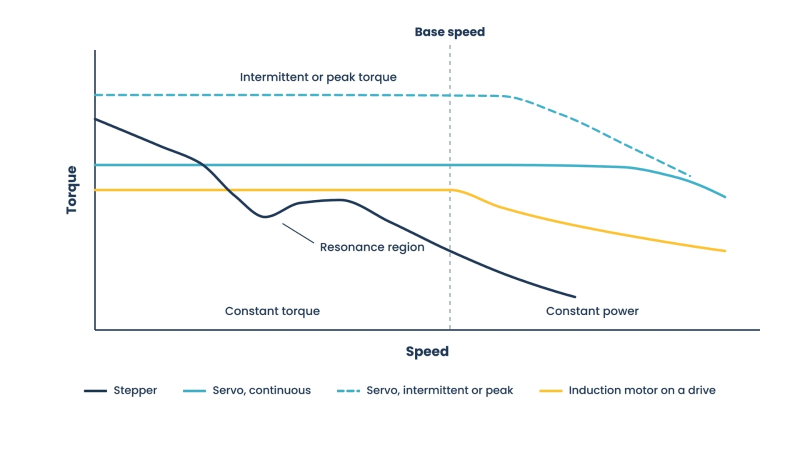
- A stepper moves in fixed increments, commonly 1.8 degrees per full step for a standard two-phase motor, and produces its highest torque at low speed. Torque falls as speed rises, because back electromotive force and winding inductance limit how fast current can be driven into the windings.
- Microstepping improves smoothness far more than it improves accuracy, and it adds no position verification. Resolution on paper is not the same as knowing where the shaft is.
- A servo maintains usable torque across its speed range and can briefly deliver a multiple of its continuous torque, which is what makes short, aggressive moves possible. It costs tuning effort, feedback hardware, and money.
- A VFD provides full torque up to base speed and constant power above that speed, making it ideal for continuous rotation. Slow continuous operation requires careful specification because self-cooled motors lose fan cooling at low speeds. What duty is actually allowable depends on the motor's thermal capability, enclosure, cooling arrangement and rating, not on the drive alone.
- Inertia ratio guidance varies widely between sources. The commonly cited target is at or below 10:1, but the real constraint is resonance in the coupling, and stiffly coupled or direct-drive systems run far higher successfully.
- Drive-based safety functions, such as safe torque off, are defined in IEC 61800-5-2 and inform a machine-level safety assessment. Safe torque off prevents the motor from producing torque. It does not isolate electrical energy, does not create a controlled stop, and does not hold a gravity load, and it is not a substitute for that assessment.
Ask three engineers which motion technology a machine needs, and you will often get three answers that reflect what each of them most recently worked on. The choice tends to be made by habit because all three technologies will produce motion, and a machine built around the wrong one usually works, in the sense that the axis moves. What it does not do is hold position under load, or accelerate fast enough to meet cycle time, or run all day at low speed without overheating, and those failures appear at commissioning rather than at design review.
The differences here are physical. A stepper, a servo, and an induction motor on a variable-frequency drive produce torque by different means, have different torque-speed curves, and differ in whether anything in the system knows where the shaft actually is. Those three facts drive almost every consequence that follows. What follows describes each technology on its own terms, including what it costs you, then gives the decision path in the order the questions should be asked. None of the three is better than the others. Each wins under conditions that can be stated plainly.
01. What actually decides this
The questions that determine the answer are not about the motor. They are about the motion the machine has to perform.
- Does the application need to reach and hold a defined position, or only to turn at a controlled speed? This single question separates the variable frequency drive from the other two more reliably than anything else.
- If position matters, does the system need to know it reached the position, or is commanding it sufficient? This separates servo from open-loop stepper.
- What is the required accuracy and repeatability at the load, not at the motor shaft, since couplings, gearing and mechanical compliance all sit in between.
- How aggressive is the motion? Acceleration rate, settling time, and the number of moves per minute the machine can complete.
- What does the torque demand look like across the speed range? Constant at all speeds, or falling away as speed drops, which is the characteristic of fan and pump loads.
- What is the duty cycle, including dwell time, since a motor sized on peak torque and a motor sized on root-mean-square torque are different motors.
- What is the load inertia relative to what the motor can present, and can gearing be used to change that relationship?
- What is the consequence of losing position or stalling, which is a safety and process question rather than a control one.
- What does the plant already run, since spares, technician familiarity, and existing drive platforms have real value that does not show up in a component comparison?
That last point is worth dwelling on. The technically optimal choice and the right choice for a given plant are not always the same, and a servo axis in a facility whose maintenance team has never tuned one carries a support cost that no datasheet shows. It is a legitimate input rather than an excuse, and it should be weighed openly instead of quietly deciding everything.
For an existing machine, add one preliminary question: are you correcting a component failure, or correcting a limitation in the original axis design? If the machine previously met its requirement and the issue is an unavailable drive, damaged motor, or aging feedback device, the lowest-risk answer may be an exact replacement, repair, or validated successor. If the machine is missing position, overheating, failing to meet cycle time, or repeatedly damaging components, the technology choice must be revisited as part of a broader review of the load, mechanics, controls, and process.
02. Stepper
What it is
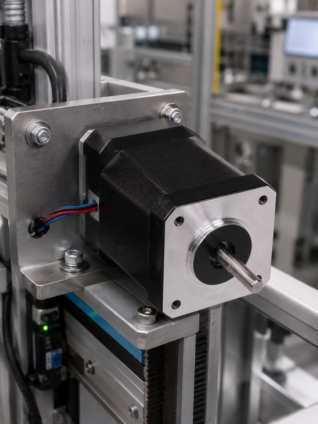
A stepper motor advances the shaft by a fixed angular increment for each command pulse. A standard two-phase motor divides a revolution into two hundred full steps, giving 1.8 degrees per step. Because the increments are fixed and known, the controller can command a position by counting pulses, with no feedback device in the loop. The motor produces holding torque at standstill without a brake, and its torque is highest at low speed.
Microstepping subdivides each full step by proportioning current between the windings. It improves smoothness, reduces audible noise, mitigates resonance, and substantially increases the number of commandable positions. What it does not do is improve accuracy in proportion, because the incremental torque available per microstep falls as the subdivision increases, and the rotor still has to overcome detent torque, friction, and load inertia before it moves at all. Nor does it add any verification: microstepping controls the current vector, not the rotor.
What it suits
- Point-to-point positioning where the move profile is known and the load is predictable.
- Applications operating mainly at low speed, where the stepper's torque characteristic is at its best.
- Holding position at standstill without a brake, which the stepper does naturally.
- Multi-axis machines where cost per axis matters and the dynamics are moderate.
- Machines built by teams without servo tuning experience, since a stepper system generally works without loop tuning.
- Applications where a stall would be an inconvenience rather than a hazard or a scrapped part.
What it costs you
Torque falls as speed rises. As the motor turns faster, the back electromotive force rises, and the winding inductance limits how quickly the current can be established, so the drive is unable to maintain the commanded current, and available torque declines. This is why a stepper chosen based on its holding torque figure can disappoint badly in an application that needs to move quickly, and why the torque-speed curve, rather than the headline torque number, is the specification that matters.
In open loop, there is no confirmation. If the load exceeds available torque at any point in the move, the rotor falls behind, and the controller does not know. Position error accumulates silently until something makes it visible, which is often a scrapped part or a crash. The common mitigation is to oversize the motor and add margin, which works and also means paying for capacity to cover an uncertainty rather than a requirement.
Steppers also exhibit resonance. The motor and load form a spring-mass system with a natural frequency, and when the step rate approaches it the rotor can oscillate rather than stepping cleanly, losing torque or stalling. Microstepping and damping help, and the effect is manageable, but it is a real constraint on the speed range within which the machine can operate.
Finally, an open-loop stepper draws current to hold position whether or not the load requires it, so it generates heat at standstill in a way a servo does not.
03. Servo
What it is
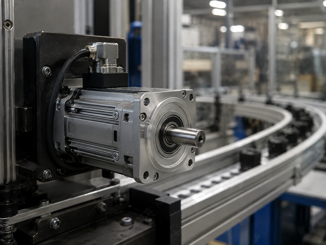
A servo system closes a control loop around a feedback device, usually an encoder or a resolver mounted to the motor and sometimes a second device on the load. The drive continuously compares commanded position, velocity or torque against measured value and corrects the difference. Because the loop is closed, the system knows its position error at all times and can fault on it rather than accumulating it.
The practical consequence is a flat usable torque band across most of the speed range, plus the ability to deliver substantially more than continuous torque for short intervals. That intermittent capability is what enables hard acceleration and short settling times, and it is shown on the torque-speed curve as a separate envelope above the continuous one.
What it suits
- Motion requiring verified position, where knowing the axis arrived matters as much as commanding it to.
- High dynamics: rapid acceleration, short moves, tight cycle times, high move rates.
- Applications needing usable torque at speed rather than only at standstill.
- Coordinated multi-axis motion, electronic gearing and camming, where axes must follow one another precisely.
- Torque control as a mode in its own right, for winding, tensioning and pressing applications.
- Applications where a following error must raise a fault rather than silently becoming a defect.
- Variable or uncertain loads, where the loop absorbs the variation instead of the engineer having to design margin for it.
What it costs you
Cost, in components and in engineering. The motor, drive, and feedback device are more expensive than the stepper equivalent, and the system requires tuning. Modern drives autotune well, and the burden is far lower than it once was, but a poorly tuned servo axis can oscillate, overshoot, settle slowly, or become unstable, and diagnosing that requires skills the maintenance team either has or does not.
Complexity carries through to support. There are more parameters to get wrong, more that can be changed by someone troubleshooting a different problem, and a feedback device and cable that constitute additional failure points. Servo systems also generate more electrical noise from high-speed switching, so grounding, shielding, and cable practices matter more than elsewhere and are a common source of intermittent faults when done casually.
There is also a design cost that buyers underestimate: a servo system exposes mechanical shortcomings. Backlash, compliance in couplings, and structural resonance that a stepper system simply pushes through will show up as instability or settling problems in a well-tuned servo loop, because the loop is fast enough to see them. This is not a fault of the servo, but it means the mechanical design must be good enough to warrant one.
04. Variable frequency drive and induction motor
What it is
A variable frequency drive controls the speed of an alternating current motor by varying the frequency and voltage supplied to it. Control strategies range from a scalar volts-per-hertz approach through sensorless vector control to closed-loop vector control with a feedback device fitted. The motor is usually an induction motor, though permanent magnet motors are also driven this way and require a control strategy suited to them.
The characteristic shape is a constant-torque region up to base speed, where the drive maintains the voltage-to-frequency relationship and the motor can produce rated torque at any speed in that range, followed by a constant-power region above base speed. In the upper region, the voltage cannot rise further; flux falls as frequency increases; available torque declines, while power remains roughly flat.
What it suits
- Continuous rotation at controlled speed: conveyors, mixers, extruders, blowers, pumps, fans, centrifuges.
- Loads following the affinity relationships, where torque varies with the square of speed and power with the cube, which is the fan and pump case and where speed control delivers its largest energy benefit.
- Higher-power applications, where the technology scales in ways steppers do not and at costs servos do not match.
- Applications wanting soft start and controlled deceleration to reduce mechanical and electrical stress.
- Plants already standardized on drives and induction motors, where spares, familiarity and drive platform commonality are real.
What it costs you
Positioning is not its natural function. Closed-loop vector control with a feedback device can perform some positioning, and this capability is genuine, but a drive and induction motor may be appropriate for lower-dynamic or less-demanding positioning, while a servo is generally the more natural candidate for high-performance, tightly coordinated position control. Choosing a drive on cost grounds for a demanding positioning application usually means accepting performance that is less than the machine needs.
Sustained low-speed operation is a specification question. A self-cooled motor relies on a shaft-mounted fan, so as speed falls, its cooling falls with it, while a constant-torque load continues to demand full current. Running slowly for long periods therefore requires either a motor with separate forced ventilation, a motor rated for that duty, or gearing that lets the motor run nearer base speed while the load runs slowly. Assuming a standard motor will maintain its rated torque at low speeds indefinitely is a recurring and expensive error. The allowable duty at reduced speed is determined by the motor's thermal capability, its inverter duty rating, enclosure and cooling arrangement, and the operating environment, so it must be established for the specific motor rather than assumed from the drive's capability.
The drive imposes electrical stresses that a sinusoidal supply does not. Fast-switching transitions, combined with cable length, can produce voltage at the motor terminals well above the supply voltage, which is why NEMA MG 1 Part 30 addresses general-purpose motors used on drives, and Part 31 covers definite-purpose inverter-fed motors with a defined insulation withstand requirement. Internationally, IEC TS 60034-25:2022, a technical specification published by the International Electrotechnical Commission covering AC electrical machines used in power drive systems, provides relevant guidance on converter-fed machine performance and installation. Whether a Part 31 motor is required is a matter for evaluation rather than a blanket rule: motor insulation, cable length, switching characteristics, supply voltage, grounding, bearing current risk, and the specific duty all bear on the decision, and motors meeting Part 31 requirements are designed for use on drives. On inverter-supplied systems, many Part 31-rated motors are marked with a 1.0 service factor, even though the same motor has a higher service factor on sinusoidal line power. Confirm the nameplate rating and the manufacturer's inverter-duty data rather than assuming overload margin is available. Related installation effects include bearing currents, which are addressed by measures such as insulated bearings or shaft grounding, and harmonic distortion drawn from the supply, which is a system-level question rather than a motor one.
Finally, drive ratings themselves are load-dependent. Constant-torque and variable-torque ratings usually describe the same hardware assessed against different thermal duty, so a drive selected only on its variable-torque rating and then applied to a constant-torque load may be thermally undersized, leading to overload trips, reduced allowable duty, or shortened life. Specify the load characteristic and required overload capability when selecting the drive.
05. The middle ground
Treating this as a clean three-way choice overstates the boundaries. Three intermediate approaches are common enough to belong in the evaluation.
Closed-loop stepper
Adding a feedback device to a stepper yields a system that lies between the two positioning technologies. Implementations vary considerably in how much they actually do. The simplest detect lost steps and command corrective steps at the end of a move, which eliminates silent position loss but does not improve dynamics. More capable implementations run the stepper under continuous current control with a position loop, which further reduces the standstill heating caused by open-loop operation and can improve available torque. When evaluating one, ask which of these it is, because the term covers both.
Closed-loop vector drives
A drive with a feedback device fitted can control an induction motor with substantially better low-speed torque and some positioning capability. This is a legitimate answer for applications that are mostly continuous rotation but occasionally require positioning, or require full torque at very low speed. It is not a substitute for a servo in a genuinely dynamic positioning application.
Direct drive
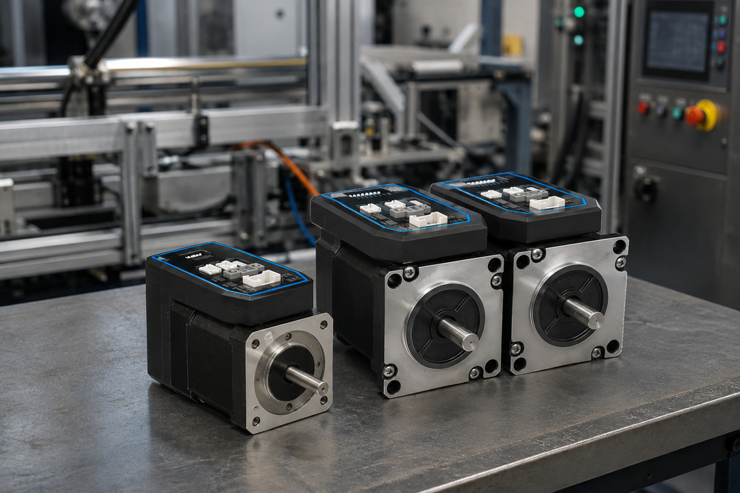
Removing the gearbox and coupling a motor directly to the load eliminates backlash and compliance, which changes the inertia discussion entirely, since the very stiff connection tolerates inertia ratios that would be unworkable through a compliant coupling. It costs torque density, and it demands a motor sized for the load's full torque without mechanical advantage. Where accuracy and settling time are the binding constraints and the torque is achievable, it is worth evaluating rather than defaulting to a geared arrangement.
06. The decision path
In this order, the questions narrow the field without requiring a preference. Where an answer is unknown, that is the work to do, not an assumption to make.
- Are you replacing an existing system? Record the installed motor and drive part numbers, supply voltage, controller interface, feedback type, mechanical mounting, brake requirements, safety connections, and operating problem before selecting an alternative. If the original axis performed adequately, first investigate repair, an exact replacement, or a supplier-validated successor. If the motion technology is changing, treat the work as a redesign and confirm the complete motor, drive, controller and mechanics combination.
- If a technology decision is genuinely required, does the application need to reach a defined position, or only to turn at a controlled speed? If speed alone, a drive and induction motor is the leading candidate and the remaining questions are about sizing, cooling and drive rating rather than technology.
- If position is required, what happens if the axis does not reach it? If the answer involves a safety consequence, scrap, or an undetected process fault, you need feedback, and the question becomes servo or closed-loop stepper.
- What accuracy and repeatability are required at the load? Work out what that demands at the motor shaft after gearing, because that is the number the technology has to deliver.
- How fast does the move need to happen, and how quickly must it settle? Aggressive acceleration and short settling times point to servo, because that is what the intermittent torque envelope and the closed loop are for.
- At what speed in the speed range does the application need its torque? High torque at low speed favors the stepper; usable torque across a wide range favors the servo; continuous rotation near base speed favors the drive.
- How many moves per unit time, and what is the duty cycle including dwell? This determines whether the sizing calculation is governed by peak or by root-mean-square torque.
- What is the reflected load inertia, and can gearing bring it into a workable relationship with the motor?
- Is the load predictable, or does it vary? Variable loads favor a closed loop because the alternative is to design margin for the worst case and pay for it in every cycle.
- What does the plant already run, and who will maintain this? Weigh this openly rather than letting it decide silently.
07. Where each option is the wrong answer
Where a stepper is wrong
- The application needs meaningful torque at higher speed, where the stepper curve has already fallen away.
- A missed position would create a hazard, scrap a part, or go undetected into the process.
- The load is variable or occasionally shock-loaded, so the margin required to guarantee no stall exceeds that of the motor you wanted to buy.
- Cycle time depends on hard acceleration, which requires the intermittent torque capability that the stepper lacks.
- The machine must run continuously at a speed near the system's resonance, and mechanical redesign to move it is not practical.
- Standstill heating is a problem, for example in a thermally sensitive enclosure or a long-dwell application.
Where a servo is wrong
- The application is continuous rotation at a controlled speed, where the closed-position loop is capacity nobody uses, and the cost is real.
- The mechanics are not good enough to support it, since backlash and compliance that a stepper pushes through will surface as instability in a fast loop.
- Nobody on site can tune or diagnose one, and no support arrangement covers that gap.
- The power level is high enough that a drive and induction motor is the natural and much cheaper technology.
- The dynamics are modest, and the load is predictable, in which case the capability is being paid for without being used.
Where a drive and induction motor is wrong
- The application requires accurate, repeatable positioning, particularly with short moves and fast settling.
- Sustained operation at low speed with a constant torque load, unless the motor is specified for it with appropriate cooling or gearing.
- Coordinated multi-axis motion, camming or electronic gearing, which is not what this technology is for.
- Torque control as a primary mode, for tensioning or pressing, where a servo does it properly.
- Applications needing controlled holding torque at zero speed, which requires either a brake or a different technology.
Where all three are the wrong question
Sometimes the motion technology is not the constraint. If the machine cannot hit its cycle time, the limiting factor may be the mechanism, the fixturing, or the process rather than the axis, and a faster axis will not help. If accuracy is the problem, backlash and compliance downstream of the motor frequently dominate anything the motor contributes. Before upgrading the technology, measure where the error or the time is actually going, because upgrading an axis that was never the bottleneck is an expensive way to learn that.
The same caution applies when a legacy drive fails. Replacing the visible failed part without checking the load, feedback, cable condition, coupling, brake, cooling, and application changes can recreate the failure in a new component. Confirm the failure mechanism before treating replacement as correction.
08. Sizing, and what to confirm with a supplier
The sizing arithmetic in outline
Sizing follows the same shape regardless of which technology is chosen. Establish the load inertia transmitted to the motor shaft, including all rotating elements in the drivetrain. Add the torque required to accelerate that inertia at the required rate, the torque to overcome friction, and any continuous load torque. That gives peak torque, which occurs during acceleration. Then compute the root-mean-square torque over the full cycle, including dwell time, which determines thermal loading.
The selection rule is that the continuous rating must exceed the root-mean-square figure, and the peak rating must exceed the instantaneous peak, both checked at the actual operating speed on the torque-speed curve rather than against the headline number. Sizing is iterative because the motor's own rotor inertia is part of the inertia being accelerated, so a preliminary selection must be made and then rechecked.
Inertia ratio, and the disagreement about it
Reflected load inertia divided by motor rotor inertia is one of the most commonly cited and most commonly misapplied numbers in motion sizing. Published guidance varies substantially. A ratio of 10:1 or lower is the most frequently repeated rule of thumb; some sources recommend staying closer to 1:1 for high-precision work, and others note that stiffly coupled and direct-drive systems run successfully at ratios far higher than either figure.
The reason for the spread is that the underlying constraint is not the ratio itself but the resonance in the mechanical connection between the motor and the load. A compliant coupling with a high inertia ratio places the system's resonant frequency within the range the servo loop is trying to operate in, which makes it difficult to tune. A very stiff connection moves that frequency out of the way, which is why direct-drive systems tolerate ratios that would be unworkable through a small helical coupling. Treat the rule of thumb as a screening test and the coupling stiffness as the actual question. No ratio is a pass or fail threshold. Final feasibility depends on the complete mechanical system, its stiffness and resonant behavior, the capability of the drive, and the tuning that can actually be achieved on the machine, so a ratio that screens out on paper may still work and one that screens in may still be untunable.
Gearing is the usual lever. Reflected inertia scales with the inverse square of the gear ratio, so a modest reduction changes the relationship dramatically and also multiplies the available torque at the load. The costs are backlash, efficiency loss, and an additional component; gearbox efficiency at start-up can differ from running efficiency, which matters in high-cycle applications.
Safety and compliance
Drive-based safety functions are defined in IEC 61800-5-2, published by the International Electrotechnical Commission, which specifies functions such as safe torque off, safe stop, and safely limited speed. These integrate into a machine-level safety design assessed in accordance with ISO 13849-1 or IEC 62061, and the drive function alone does not establish that the machine is safe. Three points about safe torque off are frequently missed. It prevents the motor from producing torque, but it does not isolate electrical energy, so hazardous voltage can remain at the drive output. It does not by itself create a controlled stop, since the load coasts rather than being brought to rest in a defined way. And it does not hold a suspended or gravitational load, which requires a brake or other mechanical means. Related product standards cover drive safety requirements generally and electromagnetic compatibility, and motor efficiency classification is addressed in the IEC 60034 series, with efficiency requirements varying by jurisdiction and revised on their own schedule.
What to confirm with a supplier
- The torque-speed curve for the specific motor and drive combination at your supply voltage, not a generic curve.
- Continuous and intermittent torque ratings, and how long the intermittent rating may be sustained.
- Motor rotor inertia, so the ratio can be calculated rather than assumed.
- For a drive: whether the rating quoted is constant torque or variable torque, and what the overload capability is at the speeds you will use.
- For sustained low-speed operation: what cooling arrangement is required and whether the motor is rated for that duty.
- Insulation and cable requirements for the drive and cable length being used, and what mitigation is recommended for bearing currents.
- For a stepper: the torque-speed curve, the resonance behavior, and whether the drive offers damping or resonance mitigation.
- For a closed-loop stepper: whether it corrects continuously through the move or only at its end.
- For a servo: what tuning support is provided, whether autotuning covers your inertia ratio, and what happens on a following-error fault.
- Which safety functions does the drive provide, to which standard, and what integration is required to use them?
- Feedback type and whether absolute position is retained through a power cycle, which determines whether the machine has to home on restart.
- Whether this is an exact replacement, a manufacturer-approved successor, or a retrofit recommendation, and what evidence supports that classification.
- What installed interfaces must remain compatible: controller command method, feedback device and protocol, motor brake, supply voltage, safety wiring, fieldbus, and mechanical mounting.
- What parameter, program, wiring, mechanical, or safety-validation changes are required before commissioning.
- The lifecycle status of the recommended motor and drive, the expected support path, and what spare strategy is appropriate for this axis.
- What the supplier has seen fail in this application type, which is the question that most reliably separates a knowledgeable supplier from a catalog.
Take This to Your Next Conversation
Eighteen questions drawn from this guide. Taken together, the answers will usually make the technology choice for you. If the need begins with a failed or obsolete component, start by establishing whether the supplier is proposing a repair, a direct replacement, a validated successor, or a retrofit. Those are different offers with different commissioning, downtime, and performance risks.
- Can you show me the torque-speed curve for this exact motor-drive combination at my supply voltage?
- What continuous and peak torque does it deliver at the speed I will actually be running?
- What is the rotor inertia, and what inertia ratio does my load give with the gearing I am proposing?
- What coupling stiffness are you assuming when you say that ratio is acceptable?
- For a stepper: what does the resonance behavior look like across my operating range, and what mitigation does the drive offer?
- For a closed-loop stepper: does it correct continuously during the move, or only detect and correct at the end?
- For a servo: does autotuning handle my inertia ratio, and what support is available if it does not?
- For a servo: what does the drive do on a following-error fault, and how is that fault reported to my controller?
- For a drive: is the rating you have quoted constant torque or variable torque, and what is my load characteristic?
- For a drive: at my lowest sustained operating speed, does this motor need separate cooling or a different rating?
- What insulation rating does the motor carry, and what does my cable length mean for voltage at the motor terminals?
- Is the feedback absolute or incremental, and will the machine have to home after a power cycle?
- Which safety functions does this drive provide, to which standard, and what do I still have to do at machine level?
- What have you seen fail in applications like mine, and what changed as a result?
- Is this an exact replacement, a manufacturer-approved successor, or a retrofit recommendation, and what evidence supports that classification?
- What installed interfaces must remain compatible: controller command method, feedback device and protocol, motor brake, supply voltage, safety wiring, fieldbus, and mechanical mounting?
- What parameter, program, wiring, mechanical, or safety-validation changes are required before commissioning?
- What is the lifecycle status of the recommended motor and drive, what is the expected support path, and what spare strategy is appropriate for this axis?
About this guide
Written by the Industrial Web Search editorial team. This guidance is general and does not replace engineering advice for a specific machine or axis. The standards referenced here are revised periodically, and their current editions are the authority. Motor efficiency requirements and machinery safety obligations vary by jurisdiction and are revised on their own schedule, and drive-based safety functions form part of a machine-level safety design rather than satisfying it on their own. Verify every specification against the current edition of the governing standard and against manufacturer documentation for the specific components, and confirm safety and regulatory obligations for your machine and market with a qualified engineer.