
The Short Version
- Specify the camera and lens based on the inspection requirement, not on a resolution figure. The smallest detectable feature, the area to be imaged, and whether the part is moving determine everything else.
- Resolution is determined by how many pixels span the smallest feature, not by the megapixel count on the datasheet. Two pixels is the theoretical sampling floor, and published guidance for defect detection commonly calls for three to five.
- Sensor format names such as 1/2-inch and 2/3-inch are a legacy convention inherited from vacuum-tube cameras and do not denote a real dimension. Use the active sensor dimensions from the datasheet for every calculation.
- The required focal length is approximately the product of the sensor dimensions and the working distance, divided by the field of view, all measured along the same axis.
- A lens has to resolve at the sensor's pixel pitch. The sensor's Nyquist frequency in line pairs per millimeter is 1000 divided by twice the pixel pitch in micrometers, and lens contrast should be checked at the field positions where features actually appear, not only at the center.
- Global shutter exposes every pixel at once. Rolling shutter reads out rows sequentially and distorts motion-induced artifacts during readout, which is a separate problem from motion blur and is not fixed by shortening the exposure alone.
- A lens mount consists of a thread and a flange, with a focal length. C-mount and CS-mount share a thread but differ by five millimeters of flange distance, so a lens can screw on perfectly and still never reach focus.
Most failed machine vision projects were specified backward. The buyer starts with a camera, usually chosen based on resolution and price, then looks for a lens that fits it, only to discover during commissioning that the system cannot see the defect it was bought to catch. By that point, the camera, the lens, the lighting, and the mounting are all wrong together, because each was chosen to suit the last rather than the part.
The correct order runs the other way. The part and the inspection task determine the required spatial resolution. Spatial resolution and the field of view fix the pixel count. The pixel count and sensor format determine the pixel pitch, which in turn determines what the lens has to resolve. The working distance and the field of view fix the focal length. Everything in a vision system is downstream of a small number of facts about the part, and a buyer who arrives with those facts settled will get a workable specification from any competent supplier. A buyer who arrives with a camera model in mind will get a quote for that camera.
01. Start from the part, not the camera
Before any component is considered, seven facts about the part and the process need to be established. Each of them constrains the specification, and none of them is a camera specification.
- The smallest feature that must be detected or measured, stated as a dimension rather than a description. A hairline crack is not a specification. Forty micrometers is.
- Whether the task is detection or measurement. Detection asks whether something is there. Measurement asks how big it is, and carries a tolerance that must be stated.
- The area that must be imaged in a single frame, including how much the part position varies from cycle to cycle.
- Whether the part is moving during acquisition and, if so, how fast.
- How much the part varies in height, both across a single part and across the population of parts.
- The space available between the lens and the part, and the mechanical envelope the camera has to fit into.
- The environment: temperature range, washdown, vibration, chemical exposure, and whether ambient light can be excluded.
The distinction between detection and measurement deserves particular attention because it affects the subsequent arithmetic. A system that reliably detects the presence of a 40-micrometer feature is not necessarily one that can measure that feature to a specified tolerance. Measurement demands both more pixel coverage and much more stable optics, and specifying one when you need the other is one of the more expensive mistakes available in this category.
Presence and absence checking, defect detection, dimensional measurement, code reading and character recognition all place different demands on the same hardware. A single station is often asked to do several of them. When that is the case, the most demanding task sets the specification, and it is worth identifying which one that is before talking to a supplier, because the answer is not always the one that feels hardest.
02. Resolution: work backward from the smallest feature
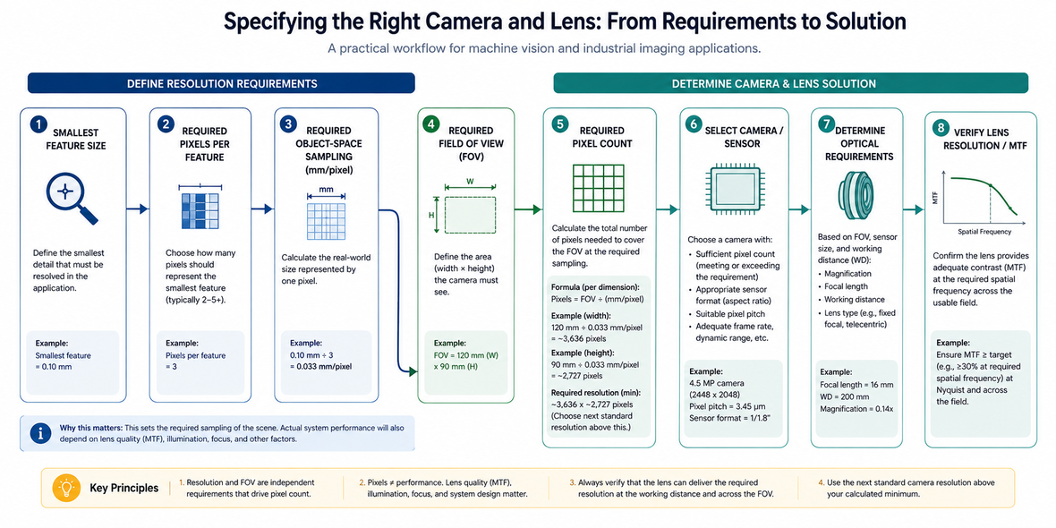
Spatial resolution is the size of the object area represented by one pixel. It is the field of view divided by the pixel count along the same axis. A 100-millimeter field of view captured across 2,000 pixels yields a spatial resolution of 0.05 millimeters per pixel. This number, not the megapixel count, is what determines what the system can see.
How many pixels a feature needs
A feature has to span more than one pixel to be sampled reliably. The Nyquist sampling limit puts the theoretical floor at two pixels, but two pixels is the edge of detectability rather than a working target. At that coverage, the recorded contrast depends on how the feature falls on the pixel grid, and any noise, defocus, or motion erases it.
Above-the-floor published guidance varies. Sources commonly recommend three to five pixels across the smallest feature for defect detection, with some placing the practical minimum at two to four and others recommending five or more where the inspection is performed by a trained model rather than a rule-based algorithm. Dimensional measurement is treated separately, and a widely used rule sizes the pixel at roughly one tenth of the required tolerance. The variation between these figures is real and reflects genuinely different applications, so the pixel coverage assumed in a quotation is a question worth asking rather than a number to take on trust.
The calculation
Work in one direction only. Take the smallest feature dimension, divide it by the pixel coverage you have settled on, and you have the maximum acceptable millimeters per pixel. Divide the field of view by that figure, and you have the minimum pixel count along that axis.
A 0.1-millimeter scratch on a part requiring a 150-millimeter field of view, with the feature 3 pixels across, needs 0.033 millimeters per pixel, which is about 4,500 pixels across the field of view. At five pixels across the feature, the same part needs about 7,500 pixels. The pixel coverage assumption changes the camera class, so it should be stated explicitly rather than left implied.
Why the number is a ceiling, not a promise
Pixel arithmetic sets the best the system could do. Whether it gets there depends on the contrast the lighting produces, the contrast the lens transmits, the accuracy of focus, and whether the part moves during exposure. Each of these raises the smallest feature the system can actually detect above the calculated figure. A configuration that has exactly enough pixels on paper and no margins elsewhere will disappoint.
The opposite error is also common and more expensive. Over-specifying resolution costs frame rate, interface bandwidth, processing time, and light, all at once. More pixels on a fixed field of view means smaller pixels, which means each one collects less light, which means longer exposures or more illumination. The usual guidance is to specify the lowest resolution that reliably meets the application requirements, with a margin, rather than the highest resolution the budget allows.
03. Field of view, working distance, and focal length
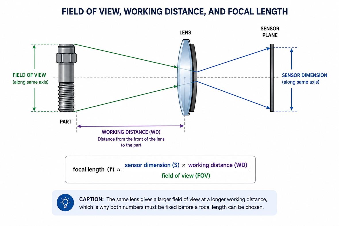
Three quantities are locked together by geometry, and fixing any two determines the third. The field of view is what has to be imaged. The working distance is the space between the front of the lens and the part. The focal length is what you buy to make those two agree.
Setting the field of view
The field of view has to cover the largest part of the population, account for variation in how that part is presented, and include a margin. Fixturing that holds a part to within a millimeter today will not necessarily do so after a year of production. Every millimeter added here costs spatial resolution proportionally, so the trade is direct and worth making deliberately rather than by rounding up.
Setting the working distance
Working distance is usually dictated by the machine rather than chosen. Guarding, the existing structure, robot travel, and access for cleaning all constrain where a camera can be mounted. Establish this number from the mechanical drawing before selecting anything, because a specification that requires a working distance the machine does not have is not a specification. Lenses also have a minimum object distance below which they cannot focus, which is a separate constraint from the one the machine imposes.
Calculating focal length
For a conventional lens, the required focal length is approximately the sensor dimension multiplied by the working distance, divided by the field of view, with the sensor dimension and the field of view measured along the same axis.
focal length ≈ (sensor dimension × working distance) ÷ field of view
The equivalent angular form gives the angle of view as twice the arctangent of the sensor dimension divided by twice the focal length, and converts that angle to a field of view at a given distance. Both forms describe the same geometry.
Three caveats apply. The approximation assumes the working distance is long compared with the focal length, which holds for most inspection work but breaks down near one-to-one magnification, where the thin lens relationship should be solved directly. Wide-angle lenses with significant barrel distortion compress the edges of the image, so the usable undistorted coverage is smaller than the calculation predicts. Fisheye lenses use a different projection model, and the formula does not apply to them at all.
Landing between available focal lengths
Fixed focal length lenses are manufactured in discrete steps, so the calculated figure will rarely match one exactly. The choice is then to move the camera slightly, accept a larger field of view and the resolution cost that comes with it, or move to the next step down and lose part of the frame. Deciding which of these is acceptable is a design decision, not a procurement detail.
Resist solving this with a variable-focal-length lens in a fixed installation. Zoom introduces a setting that can drift, be knocked, or be adjusted by someone troubleshooting a different problem, and a system whose magnification can change is a system whose calibration can silently become wrong.
04. Sensor format, pixel size, and monochrome versus color
What the format name does not tell you
Sensor formats are quoted as fractions of an inch: 1/3 inch, 1/2 inch, 2/3 inch, 1 inch. None of these fractions describes any physical dimension of the sensor. The convention was inherited from vidicon vacuum tube cameras, where the fraction referred to the outer diameter of the glass tube, and the light-sensitive area inside was roughly two-thirds of that diameter. When solid-state sensors replaced tubes, the naming was kept so that existing lenses would still be specified the same way.
The practical consequence is that a 1/2-inch sensor has a diagonal of roughly 8 millimeters, not 12.7 millimeters, with an active area of roughly 6.4 by 4.8 millimeters. A 2/3 inch sensor has a diagonal of roughly 11 millimeters. The relationship is approximately three-fifths of the true diagonal expressed in inches, but it was never standardized to a fixed millimeter value, and two sensors carrying the same format name can differ by several tenths of a millimeter between manufacturers.
Use the active area dimensions from the datasheet for every calculation in this guide. Using the format name in focal-length arithmetic yields an answer that is roughly 50% off, and it is a mistake often enough to warrant stating plainly.
Pixel size
Pixel pitch is the physical size of a single pixel, measured in micrometers. For a given sensor format, smaller pixels give more of them, and therefore more resolution across the same field of view. The costs are that each pixel collects less light, which means longer exposure or more illumination, and that the lens must resolve finer detail to make use of them. Pixel pitch is the number that connects the camera decision to the lens decision, and it appears again in section 06.
This is why megapixel count alone is a poor first question. Two cameras with the same megapixel count but different sensor formats have different pixel sizes, light sensitivities, lens requirements, and mechanical implications. The megapixel figure describes none of that.
Monochrome or color
A color sensor places a color filter over each pixel and reconstructs full color by interpolating from neighboring pixels. Because each pixel records only one color channel, the same sensor in a color variant delivers lower effective spatial resolution and lower light sensitivity than its monochrome equivalent. Most industrial inspection uses monochrome for that reason.
Specify color only where color carries information the inspection needs: verifying a component color, sorting by color, or reading a color-coded marking. When the task is to make a feature stand out, monochrome combined with a chosen illumination wavelength will usually outperform a color camera, because selecting the wavelength separates the feature from the background before the image is captured.
Comparing cameras on the same basis
EMVA 1288, published by the European Machine Vision Association and currently being elevated to an ISO standard (ISO 24942) through ISO/TC 42, defines a consistent method for characterizing sensitivity and noise, including quantum efficiency, temporal dark noise, dynamic range, saturation capacity, and signal-to-noise ratio. Manufacturers who publish results under it are reporting numbers measured the same way, which makes cameras comparable in ways marketing specifications are not. Ask whether a report is available for the specific camera model under consideration, and note that partial reporting may be available; check which measurements are included.
05. Shutter type, exposure, and parts in motion
Global and rolling shutter
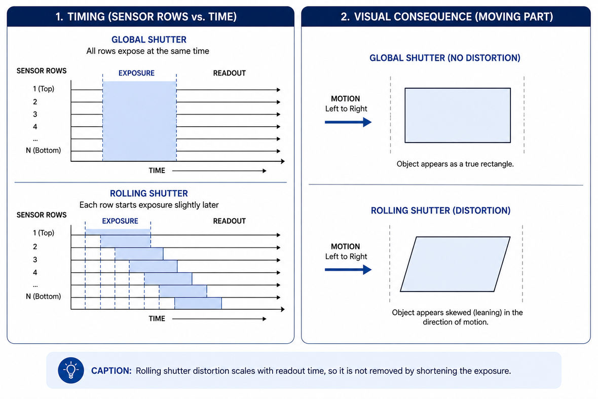
A global shutter exposes every pixel on the sensor at the same instant and reads the whole frame out afterward. A rolling shutter exposes and reads the sensor row by row, so the top of the frame is captured at a slightly different moment from the bottom. When the part or the camera moves during that readout, straight edges appear skewed and rotating features appear warped.
This is not motion blur, and it is not fixed by shortening the exposure. The distortion comes from the time offset between rows, so it scales with readout time rather than with exposure time. Faster sensor readout reduces it, and some rolling-shutter sensors offer a global reset mode in which exposure begins simultaneously across the sensor while the readout remains sequential, which reduces the artifact without eliminating it. For parts in motion, global shutter is the straightforward answer, and the cases where rolling shutter is appropriate are ones where the part is genuinely stationary at the moment of capture.
Motion blur
Motion blur is a separate effect and applies to both shutter types. It comes from the part that moves during the exposure, and the blur in object space is simply the part's speed multiplied by the exposure time. That figure needs to stay well below the millimeters-per-pixel value calculated in section 02, or the resolution specified there is theoretical. A part traveling at 500 millimeters per second with a 1-millisecond exposure moves half a millimeter during capture, which will erase any feature smaller than that, regardless of how many pixels the sensor has.
Short exposures require more light, which is why illumination cannot be treated as a separate purchase made after the camera. In practice, the answer for moving parts is usually strobed illumination synchronized to a hardware trigger, which delivers a large amount of light for a very short interval, freezing the part. Free-running acquisition, where the camera captures at its own timing rather than on a trigger from the line, is rarely appropriate for inspecting discrete parts.
Area scan and line scan
Everything above assumes an area scan camera capturing a two-dimensional frame. Line scan cameras capture a single row at a time and build an image as the part moves past, which suits continuous materials such as web, sheet, or coil, as well as cylindrical parts rotated under the camera. They give effectively unlimited length along the direction of travel and very high resolution across it. They also require encoder synchronization to the line, more demanding lighting, and different optics, so a line scan system is a different project rather than a variant of the same one. Choose line scan when the material is continuous, or the part is a cylinder, and area scan otherwise.
Frame rate and the interface
The data a camera produces is its pixel count multiplied by its bit depth multiplied by its frame rate, and the camera interface caps that figure. Raising resolution therefore lowers the achievable frame rate over a given interface, a constraint that only becomes apparent late if it is not checked early. The interface also determines cable length, whether power can be delivered over the same cable, and whether a frame grabber is required.
The interface standards themselves are maintained by different industry bodies. GigE Vision, USB3 Vision, Camera Link and Camera Link HS are hosted by the Association for Advancing Automation. CoaXPress and IIDC2 are hosted by the Japan Industrial Imaging Association. GenICam, the software layer that provides applications with a common programming interface, is hosted by the European Machine Vision Association. The five associations coordinate through a joint arrangement that also includes the German and Chinese associations. Choosing between interfaces is a decision in its own right and is treated separately; what matters at the specification stage is confirming that the interface can meet the data rate, resolution, and frame rate requirements over the cable length required for the installation.
06. Image circle, mount, and resolving power
Three properties determine whether a lens and a camera work together. Two are mechanical, and one is optical, and a lens can satisfy the mechanical requirements perfectly while failing the optical one entirely.
Image circle
A lens projects a circular image, and the sensor is a rectangular cutout of it. The image circle has to be at least as large as the sensor diagonal or the corners of the image go dark, which is vignetting. Because the edge of the image circle is also where the lens performs worst, specifying a lens rated exactly at the sensor diagonal places the sensor corners at the lens's weakest field position. Published guidance on margin varies, commonly falling between five and fifteen percent above the sensor diagonal, with the higher figure recommended where corner image quality matters to the inspection.
Lens datasheets state the image circle either as a millimeter figure or as a rated sensor format. Because format names were never standardized to a fixed millimeter value, two lenses carrying the same format rating can have image circles that differ measurably. Where margin is tight, work from the millimeter figure.
Mount
A lens mount is defined by two things: the thread or bayonet interface, and the flange focal distance, which is the distance from the mounting face to the sensor plane. Both have to match. A lens that threads on but registers at a different flange distance will not focus.
- C-mount uses a one-inch diameter thread at 32 threads per inch, with a flange focal distance of 17.526 millimeters. It is the default in machine vision and has the widest selection of focal lengths.
- CS-mount uses the same thread but has a flange focal length 5 millimeters shorter. Most sources give this as 12.526 millimeters, though some datasheets round it to 12.5. Because the threads are the same, either lens will screw onto either camera. A C-mount lens works on a CS-mount camera with a five millimeter spacer; a CS-mount lens on a C-mount camera generally cannot reach focus at all.
- TFL-mount and TFL-II mount were introduced for sensors too large for C-mount, using larger threads at the same 17.526 millimeter flange distance. They give C-mount's mechanical stability with coverage for larger formats.
- M12, also called S-mount, is a small thread used on board-level and embedded cameras. It has no standardized flange focal distance; focus is set by threading the lens in or out and locking it in place.
- F-mount, a bayonet mount carried over from photography, is used for large-format sensors where a threaded mount would be impractical.
The Japan Industrial Imaging Association publishes standards covering lens mounts for machine vision cameras, including flange focal distances and the mount sizes appropriate to given image sizes. Where a mount is unfamiliar, that is the reference to use when asking a supplier to cite.
Resolving power
The lens has to resolve detail at the scale of the sensor's pixels. The sensor's Nyquist frequency, expressed in line pairs per millimeter, is 1000 divided by twice the pixel pitch in micrometers. A 3.45 micrometer pixel gives approximately 145 line pairs per millimeter. A 1.85 micrometer pixel gives approximately 270. A lens that cannot deliver contrast at that frequency turns a high-resolution sensor into an expensive way to record blur, and no amount of processing can recover contrast the lens did not transmit.
Lens performance at a given spatial frequency is described by the modulation transfer function, which plots the proportion of scene contrast the lens transmits against spatial frequency. Reading one requires attention to three things. First, read it at the frequencies your sensor actually demands, typically checked slightly below the Nyquist rate rather than at it, since imaging right at Nyquist is unstable. Second, read it at the field positions where features appear, not only on axis, because a lens can perform well at the center and poorly at the edge of the image circle. Third, check that the sagittal and tangential curves stay close together, since a wide separation indicates astigmatism that will affect features differently depending on their orientation.
Guidance on the acceptable contrast threshold varies between sources, with figures around twenty to thirty percent commonly cited as the point below which detection becomes unreliable. The number depends on the algorithm and the image's noise, so treat it as a region to discuss rather than a line to apply.
Two warnings about datasheets. Lenses marketed by megapixel rating are describing a sensor class they were designed to cover, not measured contrast, and two lenses with the same rating can perform very differently. And the published curve is usually a design value, so the contrast an assembled lens actually delivers on a specific sensor is typically lower than the nominal figure because manufacturing tolerances and the sensor's own response both take something out.
07. Depth of field, aperture, and when a telecentric lens is required
Depth of field
Depth of field is the range of object distance over which the part stays acceptably sharp. It matters whenever the feature under inspection is not at a fixed distance from the lens: parts that vary in height, parts presented at an angle, parts that sit differently in a fixture from cycle to cycle, and parts with features at more than one level.
Depth of field increases as the aperture is stopped down, that is, as the f-number rises, and it does so in a roughly linear way over a useful range. The costs of stopping down are two. Less light reaches the sensor, thereby lengthening exposure and reintroducing the motion problem from section 05. And beyond a certain point diffraction begins to limit the finest detail the lens can form, so continuing to stop down eventually reduces the resolution the system can achieve. The result is a workable band rather than a direction of travel, and identifying that band for a given lens and pixel size is a reasonable thing to ask a supplier to demonstrate.
The important practical point is that depth of field is a specification. State the height variation the system has to tolerate, in millimeters, and ask what depth of field the proposed configuration delivers and at what aperture. A system commissioned on a flat sample and then presented with real production variation is the most common way depth of field becomes a problem after the money is spent.
Perspective error and telecentricity
A conventional lens, called entocentric, has an angular field of view. Objects farther from the lens appear smaller, exactly as they do to the eye. In a measurement application, this is a defect because a feature at a different height is magnified differently and therefore measured differently. The effect is called perspective error, or parallax, and it occurs even when the feature is perfectly in focus. Related to it, an off-axis feature at a different height also shifts sideways in the image in proportion to its height.
An object-space telecentric lens accepts only rays that are nearly parallel to the optical axis, so magnification is essentially constant across its telecentric range, regardless of where the part sits within it. This is why telecentric optics are the standard choice for dimensional measurement. Bi-telecentric designs are telecentric in both object and image space and provide the most stable measurements. Image-space telecentricity has a second benefit that matters with modern small-pixel sensors, since light arriving close to perpendicular to the sensor reduces vignetting and color shift toward the edges of the frame.
The constraint is size and cost. The front element of an object-space telecentric lens must be at least as large as the field of view it images, which makes the approach impractical for large parts and even expensive for modest ones. Where telecentric optics are not viable, the alternative is to control the geometry mechanically by fixturing the part so that the working distance does not vary, and to accept that measurement accuracy is now dependent on that fixturing.
Two distinctions are worth holding onto here. Telecentricity error and optical distortion are distinct specifications, and both can appear in a good datasheet; both affect measurement accuracy, and correcting one does not address the other. And software distortion correction is not a substitute for telecentricity, because perspective error depends on the geometry of each individual part rather than being a fixed property of the lens that can be calibrated out once.
08. How these choices constrain each other
The sections above are ordered the way the decisions cascade, and the ordering is not arbitrary. Each choice narrows the options below it, and several of them foreclose on options a buyer may not realize they are giving up.
- Choosing smaller pixels to gain resolution within a given sensor format increases the lens's required resolution and reduces the light each pixel collects. That lengthens the exposure, which brings back the motion problem, which is then solved with more illumination or a faster interface. One decision has produced three consequences.
- Enlarging the field of view reduces spatial resolution in direct proportion. Adding 20% to the field of view for fixturing tolerance removes 20% of the resolution, and if the pixel coverage was already marginal, the system has just stopped working.
- Stopping down for depth of field costs light and eventually costs resolution to diffraction. Depth of field, exposure time, and resolvable detail cannot all be maximized at once.
- Raising resolution reduces the frame rate that can be sustained over a given interface, which can turn a resolution decision into a line-speed problem or force a change in interface and cabling.
- Moving to a large sensor format to gain pixels without shrinking them pushes the system beyond the coverage of most C-mount lenses and into larger mounts, which changes the assembly's physical size and, therefore, the mechanical envelope on the machine.
- Choosing color over monochrome reduces effective resolution and sensitivity, so a color requirement identified late may require a larger sensor to recoup the cost.
Common specification errors and what they cost
- Specifying megapixels rather than pixels across the feature. Produces a camera that meets the purchase order requirements but fails inspection.
- Using the sensor format name in the focal length calculation instead of the active area dimensions. Produces a focal length that's roughly half wrong; discovered during installation.
- Pairing a high-resolution sensor with a lens that cannot resolve its pixel pitch. The extra pixels record blur, and the money spent on resolution is wasted.
- Leaving depth of field until the production parts arrive. Height variation that was invisible on the sample part causes intermittent failures that are hard to diagnose because they look like a lighting problem.
- Using a rolling shutter camera on a moving line. Produces geometric distortion that shortening the exposure does not fix and that corrupts any measurement.
- Treating illumination as a purchase to make after the camera. Lighting determines the contrast that everything else depends on, and specifying it last means specifying it around avoidable constraints.
- Sealing the camera body but not the lens, cable and connectors. An ingress protection rating applies to specific components, and an unsealed lens tube or a standard connector on a rated camera makes the rating meaningless.
- Leaving focus and iris rings unlocked on a machine that vibrates. The system is correctly specified and drifts out of specification within weeks.
- Specifying for today's part only. If part variants or line speed changes are foreseeable, the configuration should be checked against them before purchase rather than after.
09. What to send a supplier
A supplier can only specify against what they are given. The following package allows a competent supplier to return a configuration rather than a series of questions, and allows several suppliers to be compared on the same basis.
- Part drawings and physical samples where possible. Include samples that carry the defects the system must catch, especially the marginal ones. A supplier shown only good parts will specify a system that images good parts well.
- The smallest feature that must be detected or measured, dimensioned, and a statement of whether the task is detection, measurement, code reading, or classification. If it is measurement, the tolerance.
- The largest part footprint plus the placement variation, which together give the required field of view.
- The available working distance and the mechanical envelope, ideally as a drawing of the space the camera and lens have to occupy.
- Part speed, whether the part stops for inspection, and the cycle time or required throughput.
- Height variation across a single part and across the population.
- Surface finish, material, and color, since reflective, transparent, and textured surfaces all change the lighting approach and, therefore, the whole configuration.
- Ambient light conditions, and whether the station can be shrouded.
- The environment: temperature range, washdown regime, vibration, and chemical exposure.
- The required ingress protection rating, and which components it has to cover.
- Existing controls, network and platform constraints, including whether the system must integrate with vision hardware already on site.
A note on ingress protection
Ingress protection ratings are defined in IEC 60529, published by the International Electrotechnical Commission. The first digit rates protection against solids, where 6 means dust-tight. The second digit indicates protection against liquids, where 7 means immersion to a depth of 1 meter for 30 minutes. IP69K, which covers high-pressure and high-temperature washdown, is defined in a separate ISO standard rather than in IEC 60529, so a supplier citing it is citing a different document. Ratings apply to specific mechanical variants of a product rather than to a product family, and a sealed camera body protects nothing if the lens tube, cabling and connectors are not rated to match. Where washdown is involved, ask for the rating of every component in the chain.
Take This to Your Next Conversation
Fifteen questions drawn from this guide. Each has a specific answer, and a supplier who cannot give one has not finished specifying the system.
- What spatial resolution, in millimeters per pixel, does this configuration give across my field of view?
- How many pixels will fall across my smallest feature, and what pixel coverage are you assuming is sufficient for this task?
- What are the active sensor dimensions in millimeters, and what is the pixel pitch?
- Is an EMVA 1288 report available for this camera, and which measurements does it include?
- At what spatial frequency does this lens hold usable contrast, and at which field positions was that measured?
- Is that contrast figure a design value or a measured value on an assembled lens?
- What is the lens image circle in millimeters, and how much margin does that give over my sensor diagonal?
- What mount is this, what is its flange focal distance, and are any adapters or spacers involved?
- Is this sensor global shutter or rolling shutter, and if rolling, what is the full frame readout time?
- What exposure time does this configuration need with the illumination you are proposing, and how far does my part travel in that time?
- What depth of field does this give at the proposed aperture, and how was that figure arrived at?
- Does this application require telecentric optics? If not, what height variation are you assuming?
- What frame rate can this camera sustain at full resolution over the proposed interface and cable length?
- What ingress protection rating applies, which standard defines it, and does it cover the lens, cables and connectors as well as the camera body?
- If my part grows, a variant is added, or the line speeds up, which parts of this configuration still work and which have to be replaced?
About this guide
Written by the Industrial Web Search editorial team. This guidance is general and does not replace engineering advice for a specific application. Component specifications, standards, and the documents that govern them vary by manufacturer and change over time; requirements differ between installations, so verify any component's specifications against the manufacturer's current documentation and confirm environmental and regulatory requirements for your own site.