Back to All Buyer's Guides Sectors

Industrial Web Search Buyer's Guide Sector

Machine Vision & Industrial Imaging

Cameras, optics, lighting, and processing used to inspect, measure, guide, and identify parts in industrial production. This sector covers the imaging components themselves, as well as the interfaces, software, and integration that turn them into a working inspection system.

Overview

Types of Machine Vision Systems, Components, and Who Supplies Them

A working orientation to the sector is essential before comparing specific components: understanding how systems are assembled, recognizing what distinguishes the main camera types, and identifying the three types of companies you will likely engage with.

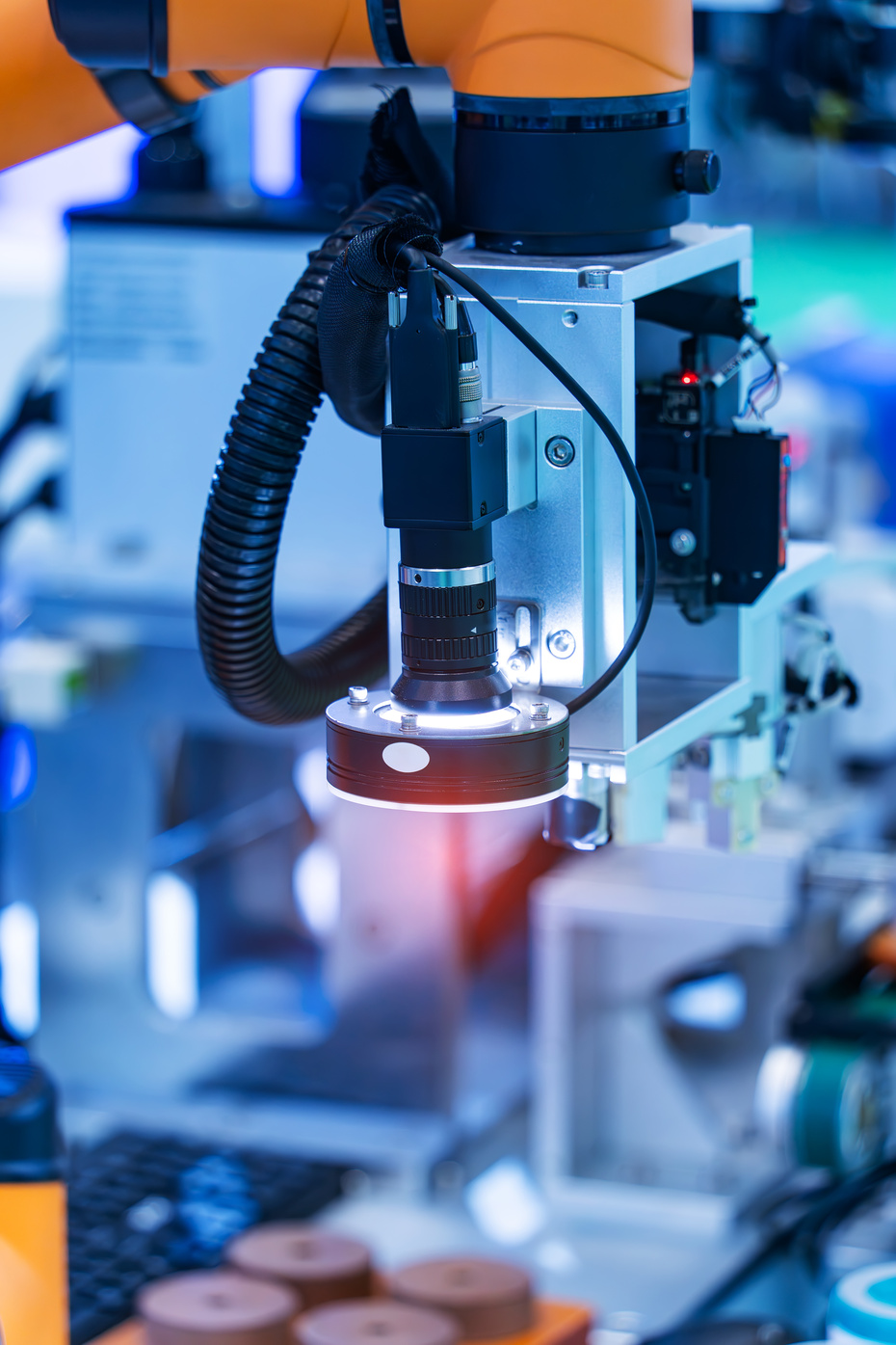
A machine vision system consists of four components working together: a camera to capture the image, a lens to focus it, lighting to illuminate the features of interest, and processing to transform the image into actionable decisions. A weakness in any of these components can limit the system's overall effectiveness, which is why relying solely on camera specifications often leads to project disappointment.

Cameras can be categorized into two main types: area scan and line scan. Area scan cameras capture a full two-dimensional image in a single exposure and are ideal for discrete parts. In contrast, line scan cameras capture one row at a time, building an image as material moves past them, making them suitable for continuous or cylindrical products, such as web and sheet materials.

Close-up of an industrial machine vision camera with an illuminated lens mounted on a robotic arm, inspecting components on an automated manufacturing line in a factory

Cameras are also differentiated by their connection methods, including GigE Vision, USB3 Vision, CoaXPress, and Camera Link. Each method varies in data transfer rates, cable lengths, camera counts, and whether a frame grabber is necessary.

There are three types of companies that operate in this sector, and understanding the differences is crucial. Component manufacturers produce cameras, lenses, lighting, or sensors. Distributors stock various components from multiple manufacturers and, ideally, also provide application engineering, sample testing, and assistance in matching optics to specific inspection needs, rather than simply shipping parts. System integrators are responsible for delivering a complete installed solution, including software, mounting, and interfacing with the production line.

Determining which type of company you need early in the process is essential, as it establishes who will bear responsibility if the system underperforms. Addressing this question is much easier before making a purchase than after.

Sourcing Considerations

How to Choose a Machine Vision System: 6 Things to Get Right

The decisions below are the ones that most often cause regret later. The detail sits in the guides at the bottom of this page.

01

Define the inspection before the hardware

State the smallest feature you must detect, the accuracy required, the part rate, and what happens on a fail. Resolution, lens, and interface all follow from those numbers. Starting from a camera specification means working backward.

02

Treat lighting as a first decision, not a last one

Lighting geometry determines whether the feature is visible at all, and no amount of resolution or software recovers contrast that was never captured. Backlight, dark field, diffuse, and coaxial each reveal different things.

03

Choose the interface for the installation

Cable management, camera quantity, and the suitability of a frame grabber typically dictate decisions before considering data rate. The fastest interface may not be appropriate if the cable cannot reach or if the host lacks a free slot.

04

Match the lens to the sensor, not just the camera

The lens must cover the sensor's image circle or the image corners go dark, and it must resolve detail at the sensor's pixel size. A high resolution sensor behind an inadequate lens gains nothing.

05

Decide who owns integration

Components, an application-support distributor, or a full integrator are three different purchases with three different risk profiles. Establish who is accountable for the system working before anything is ordered.

06

Design for the environment and for access

Vibration, ambient light, temperature, washdown, and dust all impact reliability. Physical access also plays a role; lighting and optics require space in front of the lens, and someone must be able to reach the camera for cleaning.

Glossary

Machine Vision Glossary: Key Terms Explained

The terms you will meet on a camera datasheet, a lens specification, or a system quote, in plain English.

29 terms

Area scan camera

A camera that captures a complete two-dimensional image in a single exposure. Suits discrete parts that can be presented to the camera and held still or strobed, and is the most common type in general inspection.

Backlighting

Light placed behind the object so it appears as a silhouette against a bright background. Produces very high contrast edges, which makes it the usual choice for dimensional measurement, presence checking, and detecting holes or gaps.

Bright field and dark field

Two lighting geometries defined by how the flat surface of the part appears. In bright field the light reflects off the surface into the camera, so the surface appears bright. In dark field the light strikes at a low angle and reflects away, so only scratches, edges, and texture scatter light back toward the camera.

C-mount

The most common lens mount in machine vision. A one inch diameter thread at 32 threads per inch, with a flange focal distance of 17.526 mm, covering sensors up to approximately 1.1 inch. Mount type has to match between camera and lens.

Coaxial lighting

Light directed along the same axis as the camera view, usually via a beam splitter, so that flat surfaces perpendicular to the camera reflect brightly and anything angled reflects away. Suits flat specular surfaces and highlights surface defects on them.

CS-mount and M12

Two more compact mounts. CS-mount shares the C-mount thread but sits closer to the sensor, at a flange focal distance of 12.5 mm, so fitting a C-mount lens to a CS-mount camera requires an adapter ring. M12, also called S-mount, uses a 12 mm thread with no standardized flange distance and is focused by screwing the lens in or out.

Depth of fieldDOF

The range of distance in front of and behind the focus point that remains acceptably sharp. Increased by using a smaller aperture, at the cost of light reaching the sensor. Matters whenever parts vary in height or sit at different distances from the lens.

Diffuse and dome lighting

Light scattered from many directions, commonly from a hemispherical dome with the camera looking through an aperture at the top. Removes hotspots and reflections from curved or shiny parts. Requires close proximity to the part to work properly, which constrains the mechanical design.

Dynamic range

The ratio between the largest signal a sensor can record before saturating and the noise floor at the bottom of its range. Determines whether bright and dark areas of the same scene can both be captured usefully in one exposure.

Field of viewFOV

The area the camera sees at the working distance. One of the three figures, along with sensor size and working distance, that determines the focal length of lens required.

F-mount

A larger lens mount with a flange focal distance of 46.5 mm, originally a camera manufacturer's design. Used in machine vision where a larger sensor requires a bigger image circle than C-mount optics project.

F-number

The ratio of focal length to effective aperture diameter, written as f/2.8 or similar. A smaller f-number means a wider aperture, more light, and less depth of field. A larger f-number means the reverse, which is why aperture, lighting, and depth of field are decided together.

Focal length

The property of a lens that, with sensor size and working distance, determines field of view. As a working approximation, focal length is sensor size multiplied by working distance, divided by field of view.

Frame grabber

A card installed in the host computer that receives image data from the camera. Required by CoaXPress, Camera Link, and Camera Link HS, and not required by GigE Vision or USB3 Vision. Adds cost and takes a slot, but offloads data handling from the CPU and provides precise triggering.

Frame rate and line rate

How many complete images an area scan camera captures per second, or how many rows a line scan camera captures per second. Must exceed the production rate with margin, and directly determines the data rate the interface has to carry. For line scan, required line rate depends on web speed and the desired object-space pixel size; encoder synchronization is commonly used when speed varies.

Global shutter

A sensor that exposes every pixel at the same instant. Necessary when imaging parts in motion, because the whole scene is captured at one moment rather than progressively.

Image circle

The diameter of the usable image a lens projects. If it is smaller than the sensor diagonal, the corners of the image will be dark or degraded, which is why the lens and sensor formats must be matched rather than assumed to be compatible.

Line scan camera

A camera that captures a single row of pixels at a time, building an image as the object moves past. Suits continuous materials such as web, sheet, and roll goods, as well as cylindrical parts rotated under the camera. Requires controlled motion, usually synchronized with an encoder.

Modulation transfer functionMTF

A measure of how well a lens transfers contrast at a given level of detail, usually quoted in line pairs per millimeter. The most objective way to compare whether a lens can actually resolve what a sensor is capable of recording.

Monochrome and color sensors

A color sensor places a filter mosaic, commonly a Bayer pattern, over the pixels and interpolates the missing values. A monochrome sensor of the same specification therefore resolves more genuine detail and is more sensitive. Color is specified when it carries information, not by default.

Pixel size

The physical dimension of one pixel on the sensor, in micrometers. Larger pixels gather more light and generally perform better in low light; smaller pixels allow higher resolution within the same sensor area but demand more from the lens.

Quantum efficiencyQE

The proportion of photons striking the sensor that are converted into signal, expressed as a percentage and varying with wavelength. A principal measure of sensor sensitivity and one of the parameters reported under EMVA 1288.

Rolling shutter

A sensor that exposes row by row rather than all at once. On a stationary subject this is immaterial; on a moving one it produces geometric distortion, because the object shifts between the first row being read and the last.

Sensor format

The physical size of the image sensor, quoted in fractional inch conventions such as 1/2.3", 2/3", or 1.1". It determines which lenses can cover the sensor and, with pixel count, sets the pixel size.

Signal-to-noise ratioSNR

The ratio of useful signal to background noise in an image. Low signal-to-noise makes reliable measurement and defect detection harder regardless of how many pixels the sensor has.

Smart camera and vision sensor

A camera with processing built in, running the inspection on board and outputting a result rather than an image. Simpler to deploy and lower cost than a camera plus PC, with less flexibility and less processing capacity for demanding applications.

Spatial resolution

How much real-world detail one pixel represents, usually expressed as millimeters or micrometers per pixel. Distinct from sensor resolution, which is simply the pixel count. Spatial resolution is what determines whether your smallest feature can be detected.

Telecentric lens

A lens that holds magnification effectively constant across its working range, so an object does not appear larger as it moves closer. Used for dimensional measurement, where the perspective error of a conventional lens would corrupt the result.

Working distanceWD

The distance from the front of the lens to the object being imaged. Constrained in practice by how much room exists in the machine for the camera, the lens, and the lighting in front of it.

Standards

Machine Vision Standards, Interfaces, and Environmental Ratings

What each standard governs and why a buyer should care. Which ones apply depends on your interface, your integration requirements, and the environment the camera sits in.

Camera interface standards

GigE Vision

Released in 2006 and hosted by A3, the Association for Advancing Automation, this technology operates over standard copper Ethernet cabling, and runs can reach 100 m; fiber-based implementations can go farther. It can support multiple cameras using regular network switches and does not require a frame grabber. Higher-speed Ethernet variants can increase the available bandwidth.

USB3 Vision

Released in 2013 and hosted by A3. Uses the USB 3.0 SuperSpeed interface present on most computers. Simple and cost-effective for a single camera, with cable length limited to about 5 m; longer runs need active extension, fiber, or another interface.

CoaXPress

Hosted by the Japan Industrial Imaging Association. Carries high sustained data rates over coaxial cable, with lanes able to be aggregated for more bandwidth, and supports power and triggering on the same cable. Requires a frame grabber.

Camera Link and Camera Link HS

Both hosted by A3. Camera Link is the long-established frame grabber interface; Camera Link HS was introduced to address higher speeds, particularly for line scan, and operates over copper and fiber. Both require a frame grabber.

Software and system integration

GenICam

Published by the European Machine Vision Association. A common programming interface used across the hardware interface standards, so one application can control cameras on different interfaces through the same command set. Its modules include GenApi for camera configuration, GenTL for the transport layer, and the Standard Features Naming Convention, which fixes consistent names for features such as exposure, gain, and trigger across manufacturers.

OPC UA Machine Vision

A companion specification developed by the VDMA in Germany with the OPC Foundation, published as VDMA 40100. Defines how a vision system exchanges information with a PLC, a line controller, or higher-level systems such as MES. Relevant when the inspection result has to reach the wider factory rather than stay inside the vision system.

Performance, specification, and environment

EMVA 1288 (ISO 24942)

EMVA 1288 is the established EMVA standard for camera and image-sensor characterization; its ISO adoption is in development as ISO/DIS 24942. A consistent method for measuring and reporting camera and sensor performance including quantum efficiency, dark noise, saturation capacity, and dynamic range. Its value is that results are comparable between manufacturers, which marketing figures are not. It characterizes the camera and sensor, not a system including the lens.

VDI/VDE/VDMA 2632

A German guideline series for machine vision projects, developed with VDMA Machine Vision and published in both English and German. Part 1 establishes consistent terminology so supplier and buyer mean the same thing by the same words. Part 2 sets out how to prepare a requirement specification and a system specification, which is directly useful if you are putting a project out to several suppliers and want comparable proposals.

IEC 60529 ingress protection

The international IP rating system describing protection against solids and liquids. Relevant where a camera is exposed to dust, coolant, or washdown, and the reason enclosure rating belongs in a specification rather than being assumed.

G3 and the standards bodies

Machine vision standards are coordinated globally by the G3 group, comprising A3 in North America, the EMVA in Europe, the JIIA in Japan, the VDMA in Germany, and the CMVU in China. Each standard is hosted by one of these associations, which is why ownership differs from standard to standard.

Frequently Asked Questions

Machine Vision FAQs

Direct answers to the questions buyers ask most often when sourcing in this sector.

An area scan camera captures a complete two-dimensional image in a single exposure. This type of camera is ideal for discrete parts that can be presented to it while remaining still or under strobe lighting. In contrast, a line scan camera captures one row of pixels at a time, gradually building a complete image as the object moves past it. This camera is suitable for continuous materials such as webs, sheets, and rolls, as well as cylindrical parts that rotate beneath it. Line scan operation requires precise control of the motion, typically synchronized with an encoder, and lighting that is concentrated into a bright line rather than distributed over a wide area.

The choice of camera connection is typically determined by factors such as cable length, the number of cameras, and data rate, rather than by maximum speed alone. GigE Vision operates using standard Ethernet cables over distances of up to 100 meters; it supports multiple cameras through typical network switches and does not require a frame grabber, making it a common starting point for many applications. USB3 Vision is a straightforward and cost-effective option for connecting a single camera at short ranges, although the cable length is generally limited to a few meters unless an active extension is used. CoaXPress is a high-bandwidth, low-latency, point-to-point interface commonly used where demanding data rates and deterministic triggering justify a frame grabber. Camera Link and Camera Link HS are still in use, particularly for line scan systems, but they also require a frame grabber.

When selecting a lens, three key factors must be considered: sensor size, the working distance from the lens to the object, and the desired field of view. The focal length can be roughly determined by multiplying the sensor size by the working distance and then dividing by the field of view. Additionally, the lens must meet two important conditions: its image circle must completely cover the sensor to prevent dark corners in the image, and it must have sufficient resolving power to match the sensor's pixel size. It is also essential that the lens mount type is compatible with the camera.

A telecentric lens maintains a consistent magnification across its designed working range, meaning that an object does not appear larger as it gets closer to the lens. In contrast, conventional lenses can introduce perspective errors; for instance, when a part is positioned slightly higher on a fixture, it may measure as larger than it actually is. This distinction is important when measuring dimensions, rather than simply detecting presence. Telecentric lenses tend to be larger and more expensive, and to have a fixed field of view, which is why they are primarily specified for measurement and metrology rather than for general applications.

The requirement for a frame grabber depends on the type of interface being used. GigE Vision and USB3 Vision connect to standard ports commonly found on most computers, so they do not require a frame grabber. In contrast, interfaces such as CoaXPress, Camera Link, and Camera Link HS do require a frame grabber, which is a dedicated card that receives image data. Although a frame grabber adds cost and occupies a slot on the host machine, it offloads data handling from the CPU and provides precise triggering, which is especially important at high frame rates.

A global shutter exposes every pixel on the sensor simultaneously, capturing the entire image at the same instant. In contrast, a rolling shutter exposes the sensor one row at a time, so different parts of the image are captured at slightly different times. This timing difference is insignificant for stationary objects, but with moving objects, a rolling shutter can cause geometric distortion because the object may have moved between the first and last rows captured. Therefore, applications that involve imaging moving parts typically require a global shutter.

EMVA 1288 is a standard established by the European Machine Vision Association, and it is also recognized as an ISO standard. This standard defines a consistent method for measuring and reporting the performance of cameras and sensors. It includes various parameters such as quantum efficiency, temporal dark noise, saturation capacity, and dynamic range. The main advantage of EMVA 1288 is its ability to enable direct comparisons between cameras; two cameras evaluated using EMVA 1288 can be compared accurately, unlike marketing figures from manufacturers, which may not follow a consistent method. It is important to note that this standard characterizes only the camera and sensor, not the entire system, which includes the lens.

Lighting determines whether the feature you need to inspect is visible to the camera at all. No amount of resolution or software recovers contrast that was never captured. The geometry matters more than the brightness: backlighting produces a silhouette for edge and dimensional measurement, dark field lighting strikes the surface at a low angle so scratches and texture scatter light back while the flat surface stays dark, diffuse dome lighting removes reflections from curved shiny parts, and coaxial lighting suits flat specular surfaces. Lighting is frequently specified last and is a common cause of vision projects underperforming.

Resolution follows from the smallest feature you must detect and the field of view you must cover, not from a megapixel target. Work out how many pixels are needed to resolve the smallest feature for your inspection to be reliable, then combine that with the field of view to determine the required sensor resolution. Specifying more resolution than the task needs increases data rate, cost, and processing load, and can force a more expensive interface. It also demands a lens capable of resolving that detail, since a high-resolution sensor behind an inadequate lens gains nothing.

Buyer's Guides

Guides for Selecting Machine Vision Components

In-depth guides covering the decisions above.

Buyer's Guide

Specifying the Right Camera and Lens for a Machine Vision Application

Sensor size, resolution, working distance, field of view, and how lens choice follows from the inspection requirement.

Read the guide

More coming

This sector is growing.

Additional guides are added when there is something genuinely worth saying, not on a schedule. IWS is committed to providing educational content to help you find the right suppliers!

Downloadable Resources

Machine Vision Downloads: Checklists and Reference Tools

Practical tools you can take into a supplier conversation.

Checklist

Machine Vision System RFQ Checklist

Every question a supplier needs answered before they can quote accurately, organized in the order you should work through them. Bring it to the first conversation and you will get comparable proposals instead of guesses.

Get the checklist

Find a verified machine vision supplier

Search the network for verified manufacturers, distributors, and service providers in this sector.

Every supplier verified · No pay-to-rank

Can't find it? We'll find it for you, free.

Tell us exactly what you require. Our team has spent 30+ years in industrial supply chains, and we'll track down qualified suppliers within one business day. No cost, no obligation.

Request Free Sourcing Help