The Short Version
- Three properties separate the types: surface area per unit of volume, how closely the two streams can approach each other in temperature, and how the surfaces are cleaned. Almost every selection is decided by one of those three before price is considered.
- Shell-and-tube handles the widest range of pressure, temperature, and fluid conditions, and it is the type with the deepest body of design and construction standards behind it. It pays for that with size and weight.
- Plate exchangers pack far more surface area into a given volume and achieve much closer temperature approach, which can make a duty possible that shell-and-tube exchangers cannot achieve at any reasonable size. Gasketed units are bounded by what the gaskets tolerate.
- Air-cooled units remove the cooling water problem entirely and accept a limit in exchange: a conventional dry air cooler cannot bring the process below the dry-bulb temperature of the air reaching it, and its capability moves with the weather and the season.
- Fouling is a specification, not an afterthought. The fouling allowance chosen at design determines surface area, and an exchanger designed with generous fouling margin runs oversized and can foul faster because velocities fall.
- The cleaning method should be decided before the type is. Mechanical cleaning of the tube side requires straight tubes and access; chemical cleaning requires compatible materials, and a gasketed plate unit can be opened and cleaned plate by plate.
- The thermal design is only as good as the process data behind it. Flow rates, temperatures, physical properties, allowable pressure drop, and fouling assumptions are the inputs, and a supplier cannot invent any of them.
Heat exchanger selection goes wrong in a particular way. The duty is calculated correctly, a type is chosen from habit or from what the last plant used, and the unit performs adequately on the day it is commissioned. The problems arrive later: the exchanger fouls faster than expected and cannot be cleaned without pulling it out of the line, or it cannot make the outlet temperature in August, or it turns out to need more plot space and more cooling water than anyone allowed for.
None of those are thermal design failures. They are consequences of the physical form of the equipment, and the form is what you are choosing when you choose a type. What follows describes each of the three on its own terms, including what it costs you, then gives the decision path in the order the questions should be asked. None of the three is better than the others. Each wins under conditions that can be stated plainly, and the conditions are mostly about the fluids and the site rather than about the heat transfer.
01. What actually decides this
Nine variables drive the choice. The first three do most of the work.
- The duty and the temperature program: what has to be heated or cooled, from what to what, against what other stream, and how much heat that represents.
- The approach temperature required, meaning how close the outlet of one stream must come to the inlet of the other. A close approach eliminates some types from consideration entirely.
- What is in both streams. Clean, fouling, viscous, corrosive, particulate-laden, crystallizing, or biologically active fluids each change the answer, and the two sides can differ.
- Design pressure and temperature on both sides, including any upset condition the equipment must survive.
- Allowable pressure drop on each side, which is a budget you are spending against pumping energy for the life of the plant.
- Whether a cooling medium is available. If cooling water is scarce, expensive, or requires a new tower and treatment system, the economics shift toward air.
- The available plot space, weight, and headroom, including space to pull a tube bundle or swing a cover if that is how the unit is cleaned.
- The cleaning regimen the plant can actually perform and how often the unit is expected to require it.
- The governing standards and the owner's own specifications, which frequently narrow the field before any of the above is considered.
A note on the second point, because it is the one most often discovered late. Approach temperature is not a preference. It follows from the process that different exchanger geometries can achieve fundamentally different approaches to the same duty. Establishing it early prevents a long detour through a type that was never going to work.
02. Shell-and-tube
What it is
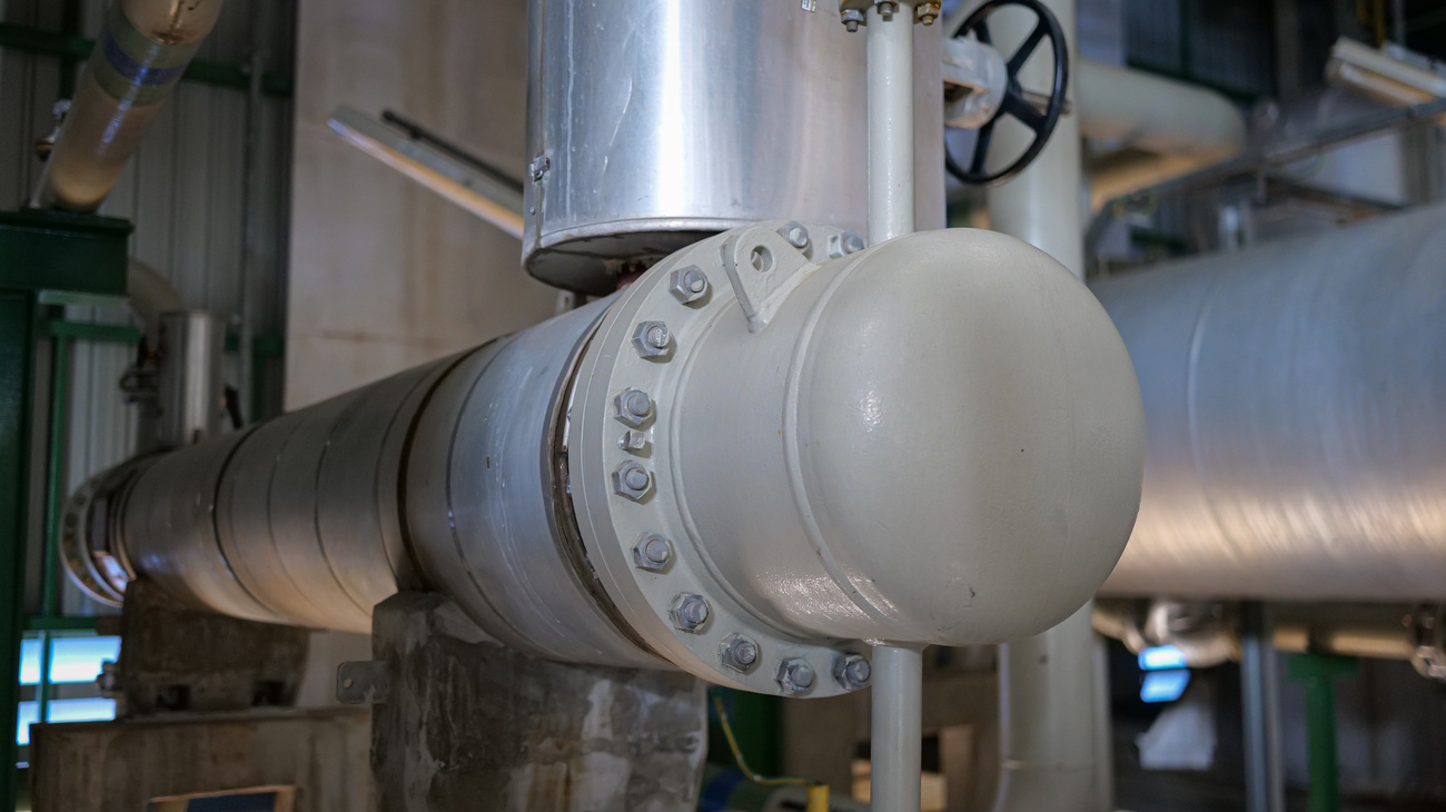
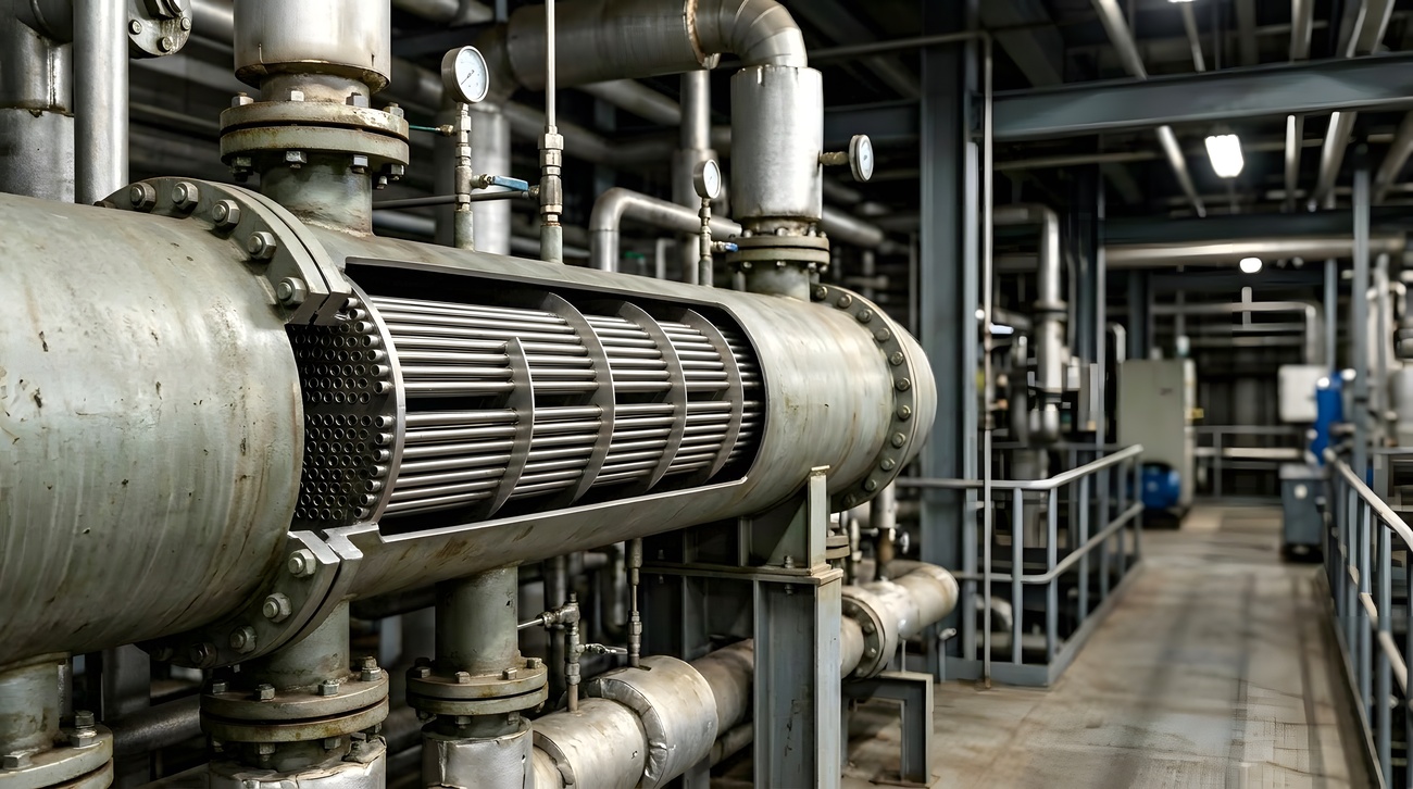
A bundle of tubes inside a cylindrical shell. One stream passes through the tubes, the other flows across the outside of them, usually directed by baffles that both support the tubes and force the shell-side flow across the bundle rather than straight along it. The construction is defined by a three-part designation covering the front head, the shell type, and the rear head, which together describe how the unit is built and how it can be opened.
The rear end arrangement matters most to a buyer. Fixed tubesheet construction is the simplest and least expensive but cannot accommodate differential thermal expansion without an expansion joint and cannot have its bundle removed. A U-tube bundle handles expansion freely and can be withdrawn, but the bends cannot be mechanically cleaned. A floating head allows both expansion and full bundle removal with straight tubes, at higher cost and complexity. That choice is effectively a maintenance decision made at the point of purchase.
What it suits
- High pressure and high temperature service, where the pressure boundary is a simple cylindrical vessel, and the design basis is well established.
- Wide temperature differences between the streams, including phase change duties such as condensing and vaporizing.
- Fouling or dirty service on the tube side, where straight tubes and a removable head allow mechanical cleaning.
- Large duties where the sheer size is acceptable and the reliability of a well-understood form is worth more than compactness.
- Aggressive fluids, since the whole range of pressure vessel materials is available and there are no elastomer seals in the primary path on welded constructions.
- Applications where a long, well-documented history of the specific configuration matters to the owner or the insurer.
What it costs you
Size and weight are the standing cost. For a given duty, a shell-and-tube unit contains far less surface per unit of volume than a plate exchanger, so it is physically larger, heavier, and needs more foundation and structural support. It also needs clear space at one end to withdraw the bundle, and that space is part of the equipment footprint even though it looks like empty floor.
Close temperature approach is difficult. Shell-side flow is not truly counterflow because the baffles force it back and forth across the bundle, and multi-pass tube arrangements introduce sections where the streams run in parallel rather than counter. The result is a limit on how close the outlet temperatures can be, and duties requiring a very close approach can drive the design toward multiple units in series or away from this type altogether.
Capacity is fixed once built. Adding duty later means a new bundle or a new exchanger, since the shell defines what fits inside it.
Finally, the shell side is harder to clean than the tube side. Mechanical access to the outside of the tubes is limited even with the bundle withdrawn, so the general rule is to place the fouling stream in the tubes where it can be reached, which in turn constrains other decisions about pressure and materials.
03. Plate
What it is
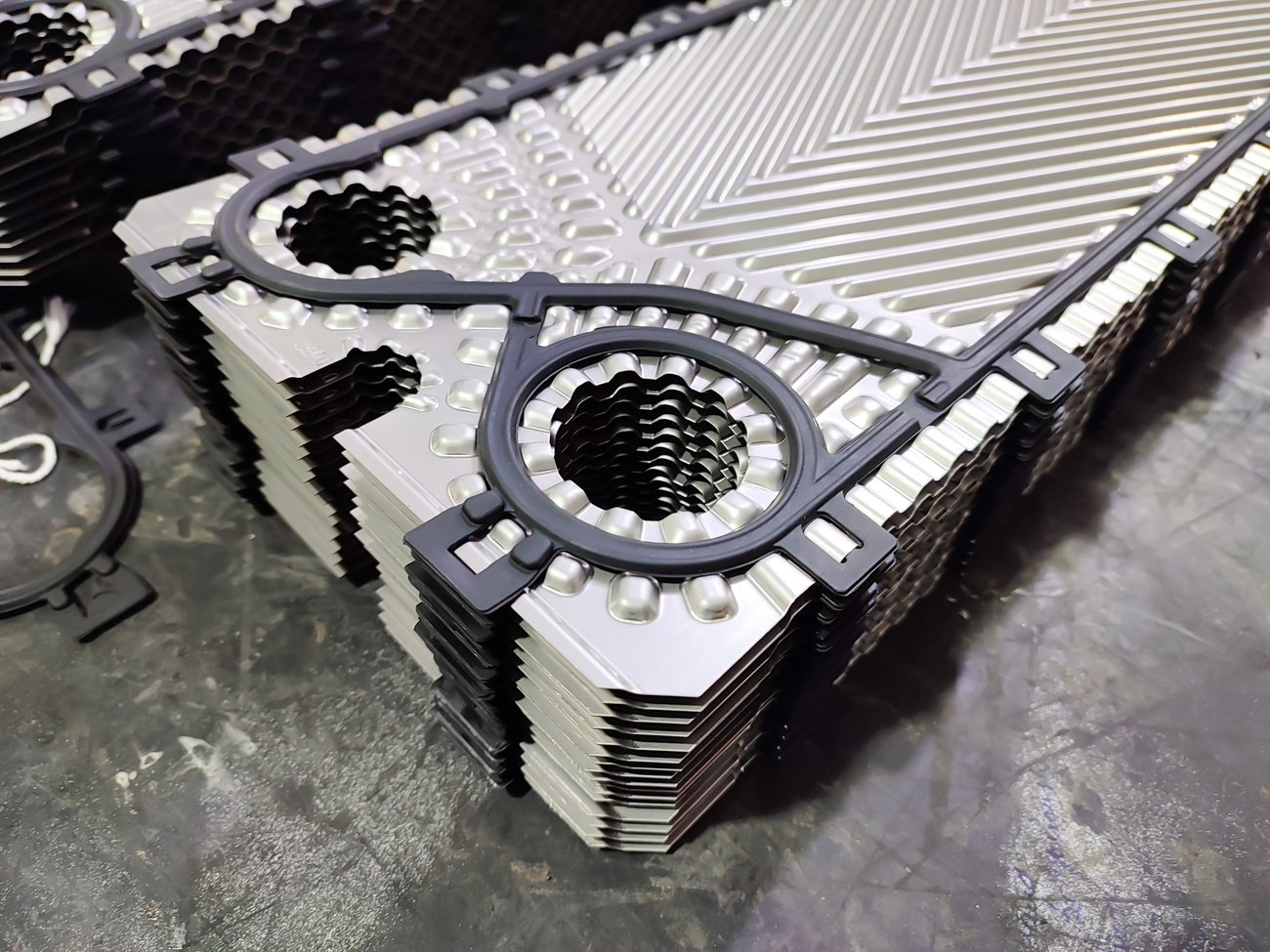
A stack of thin corrugated metal plates held in a frame, with the two streams flowing in alternate channels between adjacent plates. The corrugations create turbulence at low flow velocities and support the plates against each other, which allows very thin material to withstand significant pressure. Flow is close to true counterflow, which is the source of the type's defining advantage.
Several constructions exist, and they behave differently. Gasketed plate-and-frame units are sealed by elastomer gaskets between plates, and the pack can be opened for inspection and cleaning and altered by adding or removing plates. Brazed and fully welded units eliminate the gaskets and, with them, the ability to open the unit, extending the pressure and temperature range and the chemical compatibility. Semi-welded designs weld plate pairs and a gasket between pairs, which suits a fluid that attacks gaskets running against one that does not.
What it suits
- Duties requiring close temperature approach, which the near-counterflow arrangement makes achievable where a shell-and-tube unit would need impractical surface.
- Installations where space or weight is constrained, since the same duty occupies a fraction of the volume.
- Clean or moderately fouling liquid-to-liquid service, particularly water-to-water and process-to-water.
- Applications where duty may change, since a gasketed unit can often be re-rated by adding plates within the existing frame.
- Hygienic and food service, where the ability to open, inspect and clean every surface is a requirement rather than a convenience.
- Expensive alloys, because the thin plate material means far less metal is required for a corrosion-resistant unit than the equivalent tube bundle and shell.
What it costs you
Gaskets bound the envelope. On a gasketed unit, the pressure, temperature, and chemical limits are set by the elastomer rather than by the metal, and those limits are materially lower than a comparable welded construction. Gaskets are also a maintenance item with a service life, and a unit with many plates has a great deal of gasket length, every millimeter of which is a potential leak path. Welded and brazed constructions remove that constraint and remove openability with it.
The channels are narrow, which is the mechanism that creates the performance and also the vulnerability. Fluids carrying fibers, particulates, or anything that can bridge a narrow gap will block channels, and once blocked, the flow redistributes, and performance falls in ways that are hard to diagnose from outside. Where a plate unit is used on a duty carrying any solids, upstream straining is part of the installation rather than an accessory, and the strainer's own pressure drop, cleaning interval and plugging behavior become part of the design.
Pressure drop is generally higher for the same duty because the turbulence that yields the high transfer coefficient also introduces friction. That is a pumping cost paid continuously, and it has to be checked against the pressure-drop budget rather than assumed to be acceptable.
Finally, gasketed units are not the answer when a leak between the two streams would be unacceptable, since a gasket failure can allow one fluid to enter the other. Where cross-contamination is a safety or quality issue, that argues for a double-wall construction, a welded design, or an entirely different type.
04. Air-cooled
What it is
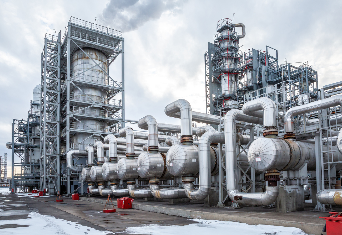
A bank of finned tubes with air blown or drawn across them by fans, rejecting heat from the process fluid directly to the atmosphere. The fins compensate for air's poor heat-transfer properties by providing a large external surface area. Fans may be below the bundle, pushing air up (forced draft), or above it, drawing air through (induced draft), and the choice affects air distribution, recirculation behavior, and the temperature the fan itself sees.
The process fluid is contained in header boxes at each end of the bundle. Header construction determines how the tubes are accessed for cleaning and plugging, with removable cover plate and plug-type arrangements offering varying degrees of access.
What it suits
- Sites where cooling water is unavailable, expensive, restricted by permit, or would require a new cooling tower and treatment system to obtain.
- Duties where the required outlet temperature sits comfortably above the design ambient, so the ambient limit is not binding.
- Remote installations without utility infrastructure, where a self-contained cooling system is worth its footprint.
- Applications where eliminating a water-side fouling and treatment problem is worth accepting an air-side one.
- Services where leakage to the atmosphere is preferable to leakage into a cooling water system that discharges to a sensitive location.
What it costs you
The binding constraint is the air temperature at the bundle. A conventional dry air cooler rejects sensible heat to the air and cannot bring the process below its dry-bulb temperature, approaching it only by a margin that costs surface area. Adiabatic, deluge, and evaporatively assisted arrangements change this by cooling or wetting the air first, which moves the achievable floor toward the wet-bulb temperature at the cost of water, treatment, and additional equipment. Note also that the temperature that matters is the air actually entering the bundle, which recirculation can raise well above the ambient the design assumed. Design is therefore done against a design ambient, and the unit's capability varies throughout the day and the year. A plant whose summer duty is set by an air-cooled exchanger has a summer capacity limit, and that has to be understood at design rather than discovered in a heat wave.
Plot space is substantial. Air-cooled bundles are large in plan area and require a clear approach for air on the inlet side and a clear discharge above; they also need to be positioned so that hot discharge air is not drawn back into the inlet. Recirculation of that kind degrades performance in exactly the conditions where performance matters most, and it is a layout problem rather than an equipment defect. Because recirculation raises inlet air temperature directly, it is a thermal design assumption as much as a layout one, and the assumption made should be stated in the quotation.
Fans mean noise and power. Sound is a specification that has to be stated with the point at which it applies, and fan power is a continuous operating cost that should be counted against the cooling water it displaces rather than ignored.
Cold weather brings its own problem. Where the process fluid could freeze, become too viscous, or drop below a dew point on the tube wall, winterization is required, whether by recirculating warm air internally, by louvers and controls, by variable or reversible fans, or by heating coils. This is a design requirement to be specified, and the minimum design air temperature is one of the inputs a supplier needs.
Finally, the air side fouls too. Dust, insects, seeds, and industrial fallout accumulate in the fins, and cleaning a finned bundle is a real maintenance task with its own access requirements.
05. Beyond the three families
Shell-and-tube, plate, and air-cooled cover the vast majority of industrial duty, which is why they form the basis of this guide. They are not the whole field, and the services most likely to produce an expensive failure are often the ones where a fourth option belongs in the conversation. If your duty appears below, ask about it explicitly rather than forcing it into one of the three.
- Wide-gap and free-flow plate designs. Plate construction with the narrow channels opened out, for fluids carrying fibers or particulates that would block a conventional plate pack while still needing the compactness and close approach that plate geometry gives.
- Spiral exchangers. Two channels wound around a center, giving a single continuous passage on each side. The geometry is self-cleaning in the sense that any local restriction raises the velocity at that point and tends to sweep the deposit away, which suits sludges, slurries, and heavily fouling liquids that would defeat both compact alternatives.
- Double-pipe and multitube hairpin units. One pipe inside another, giving true counterflow and therefore close approach in a simple, easily cleaned form. They suit small duties, high pressure, and services where a temperature cross would defeat a single shell-and-tube unit.
- Scraped-surface exchangers. A mechanical element continuously removes product from the heat transfer surface, which is the answer for crystallizing duties, very high viscosity, and products that would burn onto a static surface.
- Welded and semi-welded plate, and welded block designs. Plate performance without gasket limits for aggressive chemistry, higher temperatures and pressures, and duties where a gasketed pack would be at the edge of its envelope.
- Plate-and-shell construction. A welded plate pack inside a pressure shell, giving close approach at pressures and temperatures beyond a gasketed frame.
- Printed-circuit and diffusion-bonded designs. Very high surface density for extreme pressure and temperature service, at the cost of requiring genuinely clean fluids.
- Phase-change configurations. Kettle reboilers, thermosiphons, condensers and evaporators are selection problems in their own right rather than variants of the three families, and a boiling or condensing duty should be treated as one from the start.
The point is not that a buyer should evaluate all of these. It is that the decision path in the next section narrows within a frame, and a duty that is highly viscous, crystallizing, fibrous, sludgy, sticky or subject to a phase change may sit outside that frame entirely. Where it does, a supplier who only offers the three will fit you into the closest one.
06. The decision path
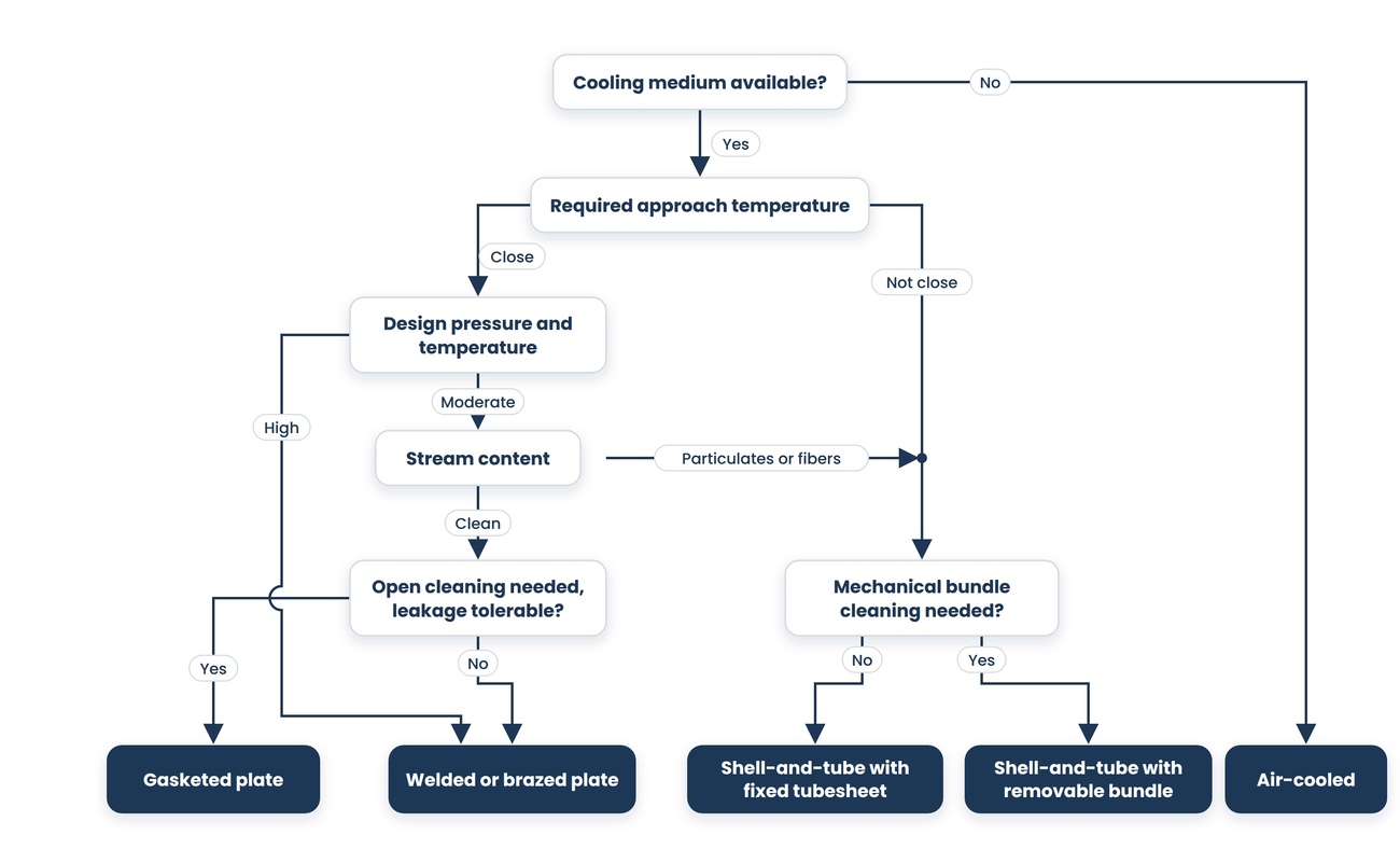
In this order, the questions narrow the field. Where an answer is unknown, that is the work to do, not an assumption to make. The path assumes your duty sits within the three families. If the previous section described your fluid, establish that before working through it.
- What is the duty and the full temperature program on both sides? Everything below depends on these being right, and they come from the process rather than from the exchanger.
- What approach temperature does the process require? A close approach points toward plate or toward multiple units in series, and away from a single shell-and-tube unit.
- Is a cooling medium available, and at what cost? If cooling water would have to be created, price the tower, the treatment, and the makeup against an air-cooled unit before assuming water is cheaper.
- What are the design pressures and temperatures on both sides? High values on either side rule out gasketed plate construction and point toward shell-and-tube or welded plate designs.
- What is in each stream? Particulates, fibers, or anything that can bridge a narrow channel rule out plate units unless it can be strained out reliably. Heavy fouling points toward straight tubes with mechanical access.
- How will the unit be cleaned, by whom, and how often? Decide this before choosing a type, because it determines rear-end construction on a shell-and-tube unit and gasketed against welded on a plate unit.
- Would leakage between the streams be acceptable? If not, gasketed plate construction needs a double-wall arrangement or a different type.
- What space, weight, and access are available, including room to withdraw a bundle or open a plate pack?
- What is the allowable pressure drop on each side, and what is pumping energy worth over the life of the unit?
07. Where each option is the wrong answer
Where shell-and-tube is wrong
- The duty requires a close temperature approach that the baffled shell side and multi-pass tube arrangement cannot deliver without unreasonable surface area.
- Space or weight is genuinely constrained, including the clearance required to withdraw a package.
- The materials required are expensive, where the mass of metal in a shell and bundle makes the unit costly compared with a thin plate.
- The duty is likely to change, since capacity is fixed by the shell.
- Fouling service is unavoidable on the shell side, where access for mechanical cleaning is poor.
Where plate is wrong
- Design pressure or temperature exceeds what the construction tolerates, which, for gasketed units, means what the gaskets tolerate rather than what the plates do.
- Either stream carries fibers, particulates, or crystallizing material that can bridge the narrow channels.
- Cross-stream leakage would be unacceptable, and a double-wall or welded construction is not being used.
- The pressure drop budget is tight because the turbulence that drives performance also generates friction.
- The fluid attacks the gasket material, which frequently limits a unit before the plate metallurgy does.
- A brazed or welded unit is proposed for a fouling duty, since it cannot be opened and cleaned.
Where air-cooled is wrong
- The approach to ambient required is so close that the surface and fan power becomes uneconomic compared to a water-cooled alternative.
- Plot space is unavailable, or the layout would force hot discharge air back into the inlet.
- Noise limits at a nearby boundary cannot be met by the fan arrangement.
- The site is dusty or subject to fallout that will foul the fin side faster than it can be cleaned.
- Summer capacity loss is unacceptable, and no supplementary cooling is planned for peak conditions.
Where the exchanger is not the problem
If an existing unit is underperforming, the cause is frequently outside the exchanger. Flow lower than design on either side, fouling well beyond the allowance, air trapped in a water circuit, a control valve throttling more than anyone realizes, or process conditions that have drifted from the original datasheet will all present as an exchanger that is not making temperature. Before specifying a replacement, measure the actual flows, temperatures and pressure drops on both sides and compare them to the design datasheet, because a new exchanger sized against the same wrong assumptions will disappoint the same way.
08. Thermal design, fouling and the data you must supply
The supplier cannot invent the process data
Thermal design is performed based on the numbers you provide, and the quality of the result is bounded by the quality of those numbers. A supplier needs the full flow picture rather than a single number: normal, minimum, and maximum flow; the startup case; the turndown the unit must hold; and any upset condition it must survive. It needs inlet and outlet temperatures, and physical properties for both streams, meaning density, specific heat, thermal conductivity, and viscosity, evaluated across the temperature range rather than at one point. Where either stream carries solids, it needs the loading and the particle-size distribution because those determine channel geometry and velocity limits before anything else. Where a phase change is involved, the design needs the pressure and the condensing or boiling behavior, not just the endpoints.
Where properties are estimated rather than measured, say so. A design built on an assumed viscosity for a fluid that turns out to be substantially thicker at the cold end will underperform, and the supplier who assumed it had no way to know.
Who supplies what
Three parties contribute to a thermal design, and confusion among them leads to incomplete inquiries. You supply the process conditions and constraints: flows, temperatures, what is in the streams, the available space, the available pressure, and the operating pattern. A process engineer, yours or a consultant, establishes duty, physical properties and the allowable operating envelope. The exchanger vendor optimizes configuration, surface, pass arrangement and materials within those, and tells you where your constraints conflict. A vendor asked to supply the first two categories is guessing, and will price the guess conservatively.
Fouling is the largest single assumption
Fouling resistance is incorporated into the design to represent deposits that will build up on the surfaces over time. It directly increases the required surface area, so the fouling allowance is one of the biggest levers for the unit's size and cost. It is also frequently applied from a table rather than from knowledge of the specific service.
Two failure modes follow, in opposite directions. Too little allowance produces a unit that meets duty when clean but fails to do so within months. Too much produces an oversized unit that runs at a lower velocity when clean, and lower velocity encourages deposition, so an overly generous fouling allowance can make fouling worse rather than better. Discuss the basis for the number rather than accepting a default, and where the service is genuinely uncertain, consider designing for a cleaning interval instead of designing for the worst case.
Two further inputs make a fouling allowance defensible rather than arbitrary. State the run length you need between cleanings, because fouling resistance without a target interval is a number with no requirement attached. And state how much performance degradation you will accept before the unit is taken out for cleaning, since that determines whether the design has to meet duty at end-of-run condition or merely at some point before it.
Those two figures also change the conversation with a supplier. A fouling resistance taken from a table describes an assumption. A run length and an acceptable degradation describe a requirement, and a supplier can design against a requirement.
Pressure drop is often a constraint rather than a budget
Higher velocity leads to better heat transfer, less fouling, and greater pressure drop. The allowable pressure drop you state, therefore, determines how aggressively the designer can use velocity, and stating it too conservatively results in a larger, more fouling-prone unit.
The important question is whether that figure is yours to choose. On a new system it may be, and it will be spent in pumping energy for the life of the installation. On an existing system, it frequently is not: the available head is set by an already-installed pump, and what remains after the rest of the circuit is what the exchanger gets. Control valve authority, cavitation margin at the pump suction, and any minimum flow requirement further narrow it. Establish which situation you are in before stating a number, because a figure invented to sound reasonable will produce a design that the pump cannot actually deliver flow through.
State the allowable drop at clean condition and at the fouled condition you are designing to, since those are different numbers and the second is the one the system has to live with at the end of a run.
Margin
Ask what thermal margin is in the proposed design, and on what basis. Some margin is prudent. Margin stacked on top of a conservative fouling allowance on top of conservative properties produces a unit substantially larger than the duty requires, which costs money at purchase and can perform worse in service because everything runs slower than intended.
09. Standards, testing and what to confirm with a supplier
The standards that govern
- The ASME Boiler and Pressure Vessel Code, published by the American Society of Mechanical Engineers, governs construction of the pressure-containing parts. Section VIII covers pressure vessels, with Division 1 the usual basis for this equipment and Division 2 an alternative set of rules. A unit built and stamped to code provides evidence that the materials, design calculations, welding, and inspection met the code requirements.
- The Standards of the Tubular Exchanger Manufacturers Association cover shell-and-tube design, construction, nomenclature and tolerances. They define three classes of service: Class R for the more severe requirements of petroleum and related processing, Class C for moderate general commercial service, and Class B for chemical process service. The class is a specification decision, not a quality grade, and it should be stated.
- API 660, published by the American Petroleum Institute, covers shell-and-tube exchangers for petroleum, petrochemical, and natural gas service. It builds on the TEMA and ASME requirements rather than replacing them, incorporating the more demanding TEMA class, and is unusually complete in specifying what the purchaser should specify and what the supplier should submit, including proposal content, drawings and document submittals after award, and spare parts.
- API 661 covers air-cooled heat exchangers for the same industries, addressing bundle and header construction, fan arrangement, sound measurement, minimum design air temperature and winterization, and internal recirculation.
- API 662 covers plate heat exchangers for the same industries.
- Where the streams are water and steam in power and similar service, the standards published by the Heat Exchange Institute are the customary basis, and they extend to equipment built under other sections of the ASME code.
- Where expansion joints are involved, the standards of the Expansion Joint Manufacturers Association apply, and where the service is sour, materials requirements come from the applicable NACE and ISO materials standard.
- Outside North America, the pressure equipment framework differs, and a European project will be specified under its own directive and harmonized standards. Mixing clauses from two frameworks into a single specification produces a document nobody can build to.
What to confirm with a supplier
- The completed datasheet for the proposed unit, showing what was assumed for every process input you did not supply.
- The fouling resistances used on each side, and the basis for them.
- The thermal margin included, and how it was arrived at.
- Calculated pressure drop on each side against the allowable figure you stated.
- For shell-and-tube: the construction designation, which rear end arrangement is proposed, and what that implies for expansion and bundle removal.
- For shell-and-tube: which side the fouling stream is on, and why.
- For plate: the plate and gasket materials, and the pressure and temperature limits of the gasket rather than of the plate.
- For plate: whether the frame has capacity for additional plates if duty increases.
- For air-cooled: the design ambient used, and what the unit delivers at the highest ambient you expect.
- For air-cooled: winterization provisions and the minimum design air temperature they are based on.
- For air-cooled: sound level, at what distance and to what method, and the layout assumptions made about recirculation.
- The code and standards to which the unit will be built and tested, named individually and drawn from a single framework.
- Required inspection and testing, including hydrostatic test, any nondestructive examination, and whether any of it is to be witnessed.
- Cleaning access required, and the clear space the installation must reserve for it.
- The closest operating reference to your service, with its run length between cleanings, the cleaning method used, the installed pressure drops, and what changed after the first turnaround. This is the question a catalog cannot answer, and the gap between design fouling and actual fouling is usually visible in it.
- Under what condition is the thermal performance guaranteed: clean, at the design fouling resistance, or at end-of-run? These are materially different guarantees, and the difference is not always volunteered.
- Whether the exchanger can be isolated, vented, drained, and cleaned without shutting down the wider unit, and which valves, bypasses, and connections the installation must provide for that.
- What the unit delivers after a partial failure: plugged tubes in an air-cooled bundle, one fan out of service, a leaking gasket in a plate pack, or a loss of cooling water on the utility side.
Take This to Your Next Conversation
Sixteen questions drawn from this guide. The answers together will usually settle the type and expose any assumption you did not make yourself.
- Which process data did you assume I did not supply, and where would the design be sensitive if those assumptions were wrong?
- What fouling resistance did you use on each side, and what is that number based on?
- How much thermal margin is in this design, and is it on top of the fouling allowance or included in it?
- What pressure drop does this give on each side, compared to the figures I stated?
- What approach temperature does this achieve, and how close is that to the limit of this geometry?
- For shell-and-tube: which construction and rear end arrangement is this, and what does that mean for expansion and bundle removal?
- For shell-and-tube: which stream is on the tube side and why?
- For plate: what are the gasket material limits on pressure, temperature, and chemical compatibility, and how do they compare to the plate limits?
- For plate: what happens if a gasket fails, and can either stream reach the other?
- For plate: can this frame take more plates if my duty increases?
- For air-cooled: what design ambient did you use, and what does the unit deliver at my highest expected ambient?
- At what condition is this performance guaranteed: clean, at design fouling, or at end-of-run?
- What run length between cleanings does this design support at my conditions, and what did the closest operating reference actually achieve?
- What clear space does this unit need for cleaning and maintenance, beyond its own dimensions?
- Which code and standards is this built and tested to, and are any clauses drawn from a different framework?
- Can you show me your closest operating reference for this service, including its cleaning interval, cleaning method, installed pressure drops, and what changed after the first turnaround?
About this guide
Written by the Industrial Web Search editorial team. This guidance is general and does not replace thermal and mechanical design for a specific service. The codes and standards referenced here are revised periodically and their current editions are the authority; the North American and European pressure equipment frameworks are distinct rather than interchangeable. Material requirements for corrosive and sour service and inspection obligations for pressure equipment vary by jurisdiction and by service. Verify every specification against the current edition of the governing document and against manufacturer documentation for the specific unit, and confirm code and regulatory requirements with a qualified engineer and the authority having jurisdiction for your site.