The Short Version
- Hydraulic fluid is effectively incompressible, and air is not. That difference produces everything else: hydraulic systems are stiff and hold position under changing load; pneumatic systems are springy and do not.
- Hydraulics deliver far more force per actuator size because they operate at much higher pressures. Where force density or space is the constraint, this usually settles the question.
- Pneumatics are cheaper to install, faster in simple motion, tolerant of stalling, and clean if they leak. They are also the more expensive of the two to run, because generating compressed air is inefficient and leaks are invisible.
- Fluid cleanliness is the dominant reliability variable in hydraulics. Most component failures trace to contamination, and cleanliness is specified as a target with a filtration system designed to hold it, not left to whatever the filter happens to achieve.
- Air quality is the pneumatic equivalent. Moisture, oil carryover, and particulate matter destroy valves and actuators, and the required treatment depends on what the air touches.
- Both store energy that remains after the machine is switched off. Accumulators and receivers hold pressure, and isolation, discharge, and lockout are design requirements rather than procedures somebody writes later.
- For many actuation duties, an electric actuator now beats both. If your requirement is controlled positioning of a moderate load, that comparison belongs in the evaluation rather than being ruled out by habit.
The choice between hydraulics and pneumatics is frequently made by inheritance. The plant has compressed air, so the machine uses cylinders. The previous machine was hydraulic, so this one is too. That works often enough to become a habit. It stops working the moment the application needs something the inherited technology does not naturally provide: a held position under varying load, a force the available cylinder cannot produce, a running cost somebody has started to measure, or a clean environment that will not tolerate an oil leak.
The two technologies differ in one physical property and inherit everything else from it. Hydraulic fluid compresses only slightly, so a hydraulic actuator behaves like a stiff mechanical link and will hold its position against a changing load. Air compresses considerably, so a pneumatic actuator behaves like a spring, which makes it forgiving, fast, and poor at stopping anywhere except the ends of its stroke. What follows describes each on its own terms, including what it costs you, adds the electric alternative that increasingly displaces both, and then gives the decision path in the order the questions should be asked.
01. What actually decides this
Two questions settle most of this, and both are worth answering before reading any further.
- Does the actuator have to hold or control an intermediate position, and does the load on it change while it does? This is the requirement that most often eliminates pneumatics, and it is frequently discovered after a machine is built rather than before.
- What force is required, and in what space? Force density is where the two technologies differ most starkly, and section 02 gives the pressure ranges that let you settle it arithmetically rather than by asking.
The remaining variables are addressed within an ordered decision path in section 05. Existing infrastructure is a legitimate advantage and belongs in that path rather than deciding in advance: a system chosen because the air main already reaches that corner of the building can cost more in energy over its life than the pipework would have, and section 07 gives you a way to price it.
02. Hydraulic
What it is
A hydraulic system uses a pump to pressurize a liquid that compresses very little, transmitting force through valves to actuators. Because the fluid barely compresses, the actuator is stiff: it resists a changing load rather than yielding to it; it can be stopped and controlled anywhere in its stroke, and its motion can be regulated precisely with the right valving.
Two qualifications belong with that, and both are circuit questions rather than properties of the technology. Holding a position and stopping at one are different problems: a cylinder parked on a conventional closed-center spool valve will drift, because spool valves leak across the lands by design, and the drift worsens as the valve wears and as the oil thins when hot. Genuinely holding a load over a shift or overnight requires a pilot-operated check valve or a counterbalance valve in the circuit, which entails its own cost and stability considerations. A machine that has crept down by morning is among the most common complaints about hydraulic equipment, and it is prevented at the circuit design stage or not at all.
The stiffness itself is also a practical rather than a theoretical figure. Entrained air in the fluid and the expansion of flexible hose under pressure both add compliance and, in real-world terms, usually dominate the oil's compressibility. A system that feels soft is more often carrying air or long hose runs than suffering from the fluid.
The other consequence is force density. Hydraulic systems operate at pressures far above pneumatic systems, so a hydraulic cylinder produces far more force than a pneumatic cylinder of the same bore. Where force is the requirement and space is limited, that is usually decisive on its own.
The pressure ratio, and why it settles the force question
The force an actuator produces is its effective area multiplied by the pressure acting on it, so the pressure at which each technology operates determines the force available from a given bore. Industrial pneumatic systems typically run at supply pressures in the region of six to eight bar, roughly ninety to a hundred and twenty psi. Industrial hydraulic systems typically operate at pressures of 150 to 350 bar (roughly 2,000 to 5,000 psi), with mobile and specialist equipment operating at higher pressures.
The practical consequence is that you can do it yourself before contacting anyone. For the same bore, a hydraulic cylinder produces force of the order of twenty to fifty times that of a pneumatic one, so a pneumatic cylinder matching a modest hydraulic one on force would need a bore several times larger and would consume air in proportion. Where the force is high, and the envelope is constrained, that ratio settles the question without involving a supplier.
What it suits
- High force and high torque duty, particularly where the actuator has to fit into a confined envelope.
- Holding or controlling intermediate positions, and holding a load statically without consuming power to do it.
- Loads that vary during the stroke, where a stiff system maintains position and speed while a compliant one does not.
- Controlled motion: precise speed control, smooth acceleration, and coordinated movement between multiple actuators.
- Applications requiring the actuator to stall against a load and hold there, which hydraulics do without damage.
- Heavy mobile and industrial equipment, where the power-to-weight advantage of the actuator matters.
What it costs you
Contamination is the dominant reliability issue and deserves its own section, section 07. The short version is that hydraulic components have close-fitting moving parts and the fluid carries whatever is in the system through all of them, so cleanliness is a design requirement rather than a maintenance habit.
Leaks are the second cost, and they are different in kind from pneumatic leaks. A hydraulic leak is visible, messy, a slip hazard, an environmental issue, and in some settings a fire risk. It also means the system is losing the working medium rather than just energy. In food, pharmaceutical, cleanroom, and some packaging environments, that consequence alone rules out the technology or forces a change to a food-grade or fire-resistant fluid, with its own compatibility implications.
The infrastructure is more substantial. A hydraulic system needs a power unit with a reservoir, a pump and driver, filtration, cooling in many cases, and instrumentation. That unit occupies space, makes noise, and generates heat on a machine that needs one actuator; that overhead can exceed the value of the hydraulic advantage.
Heat is a real design consideration. Energy lost through relief valves and throttling is carried away as heat in the fluid, and hot fluid degrades, loses viscosity, and shortens component life. Cooling capacity is part of the design, not an accessory.
Finally, the maintenance is more specialized. Fluid analysis, filter changes, contamination control during component replacement, and safe handling of stored energy all require a level of discipline that not every operation has, and a casually maintained hydraulic system will not deliver the reliability the technology is capable of.
03. Pneumatic
What it is
A pneumatic system uses compressed air, typically generated centrally and distributed around a plant, to drive actuators through valves. Air compression makes the actuator compliant: it will absorb shock, stall against an obstruction without damage, and fail to hold a precise intermediate position when the load changes.
What it suits
- Fast, simple, repetitive motion between end positions, which is the bulk of industrial pneumatic duty.
- Applications where a plant air system already exists, since the marginal cost of adding an actuator is small.
- Clean environments where the working medium is air rather than oil, provided the air is appropriately treated.
- Duties where compliance is useful: clamping, pressing against a variable surface, absorbing shock, or stalling against an end stop without harm.
- Hazardous areas, where a pneumatic actuator avoids the electrical ignition question entirely.
- Applications where components must be small, light, and inexpensive, and where the actuator may be sacrificial.
- Wash-down and high humidity environments, where robust simple hardware tolerates conditions that electronics do not.
What it costs you
Compliance is the defining limitation. Because air compresses, a pneumatic actuator behaves like a spring: it will not hold an intermediate position accurately under changing load, its speed varies with load through the stroke, and stopping it mid-stroke requires additional hardware and still does not produce hydraulic stiffness. Where a machine needs positional control rather than end-to-end motion, this constraint determines the outcome.
Force is limited by the available pressure, which is much lower than that of hydraulics. Producing significant force means a large bore, and a large bore consumes a great deal of air, which brings the running cost problem into direct view.
Running cost is the issue buyers most consistently underestimate. Generating compressed air is an inefficient conversion of electrical energy; most of the input is converted into heat rather than useful work, and the losses are distributed across compression, treatment, distribution, and the actuator itself. Compressed air is therefore an expensive utility per unit of work delivered, and its cost lands on the plant electricity bill rather than on the machine, which is precisely why it is so often ignored during a machine purchase.
Leaks compound that. A pneumatic leak is invisible and inaudible in a noisy plant; it does not stop the machine from working, and so it persists. Leakage from an established pneumatic installation is routinely a significant fraction of total air production, and every unit of it is continuously paid for. That is a maintenance and management problem rather than a technology fault, but it is a real cost of choosing the technology.
Finally, exhaust noise is a genuine nuisance requiring silencers, and air quality must be managed. Moisture, compressor oil carryover, and particulate matter degrade valves and actuators; treatment is required, not optional.
What you can do about the running cost
The cost disadvantage described above is real and not fixed. Five levers are available to a buyer specifying a pneumatic machine; most are cheap, and all are easier to apply at purchase than afterward.
- System pressure. Every bar of distribution pressure costs compressor energy and increases the leakage rate through every existing leak, so a plant running higher than it needs pays twice. A single poorly specified machine often drives high settings. If you are buying that machine, its pressure requirements have consequences across the whole network, and asking whether it can operate at the normal plant pressure is a legitimate question.
- Dual-pressure circuits. Most cylinders require full force in only one direction, and running the return stroke at a reduced, regulated pressure is a standard arrangement that reduces consumption without affecting function. It can be required in the specification.
- Sizing basis. Oversized cylinders and oversized tubing are the usual cause of high consumption, and asking a supplier to state the sizing basis, including the assumed force and the safety margin applied, is a reasonable inquiry rather than an intrusion.
- The marginal cost question. Whether adding this machine to an existing air system is cost-effective depends on whether the compressor is near capacity, whether it is fixed- or variable-speed, and how it behaves when unloaded. A fixed-speed compressor with spare capacity may add the machine at modest cost; one already near capacity may force another compressor. This is the question that the infrastructure quantification in section 05 actually turns on.
- Local receivers. An actuator with a high instantaneous demand at the end of a long line is starved not by the compressor but by the pipework, and a receiver close to the actuator fixes it more cheaply than upsizing the main. This is the named remedy for the starved actuator symptom described in section 06.
04. The third option
Presenting this as a two-way choice reflects how the question is usually asked rather than what the market now offers. For a substantial category of duty, an electric actuator beats both, and leaving it out of the evaluation is the most common way a fluid power decision can go wrong before it even starts.
Where electric actuation wins
- Controlled positioning of a moderate load, where a servo- or stepper-driven actuator gives precise position, velocity, and force control with feedback and diagnostics that neither fluid technology provides natively.
- Applications where energy is consumed only during motion, since an electric actuator draws nothing while idle and a hydraulic power unit or a compressor continues to run.
- Environments where hydraulic fluid is unacceptable and pneumatic precision is inadequate.
- Machines where programmable, changeable motion profiles are valuable, since changing a move in software is cheaper than changing hardware.
Where fluid power still wins
- High force in a small envelope, where hydraulics remain unmatched.
- Very high cycle rates on simple motion, where pneumatics are cheap and fast.
- Stalling against a load indefinitely, which fluid systems tolerate and electric actuators generally do not without additional provision.
- Harsh environments, wash-down and hazardous areas, where robust fluid hardware often outlasts electronics.
- Shock loading, where compliance protects the machine.
How to handle it in an inquiry
Where the duty is controlled positioning of a moderate load at a moderate cycle rate, ask for all three to be quoted and compare them on total cost, including energy over the expected life rather than on installed cost. The answer is genuinely mixed, and the point is that the comparison should be made rather than assumed. Where the duty is high force, very high cycle rate, or a difficult environment, fluid power usually remains the answer, and the comparison is quick.
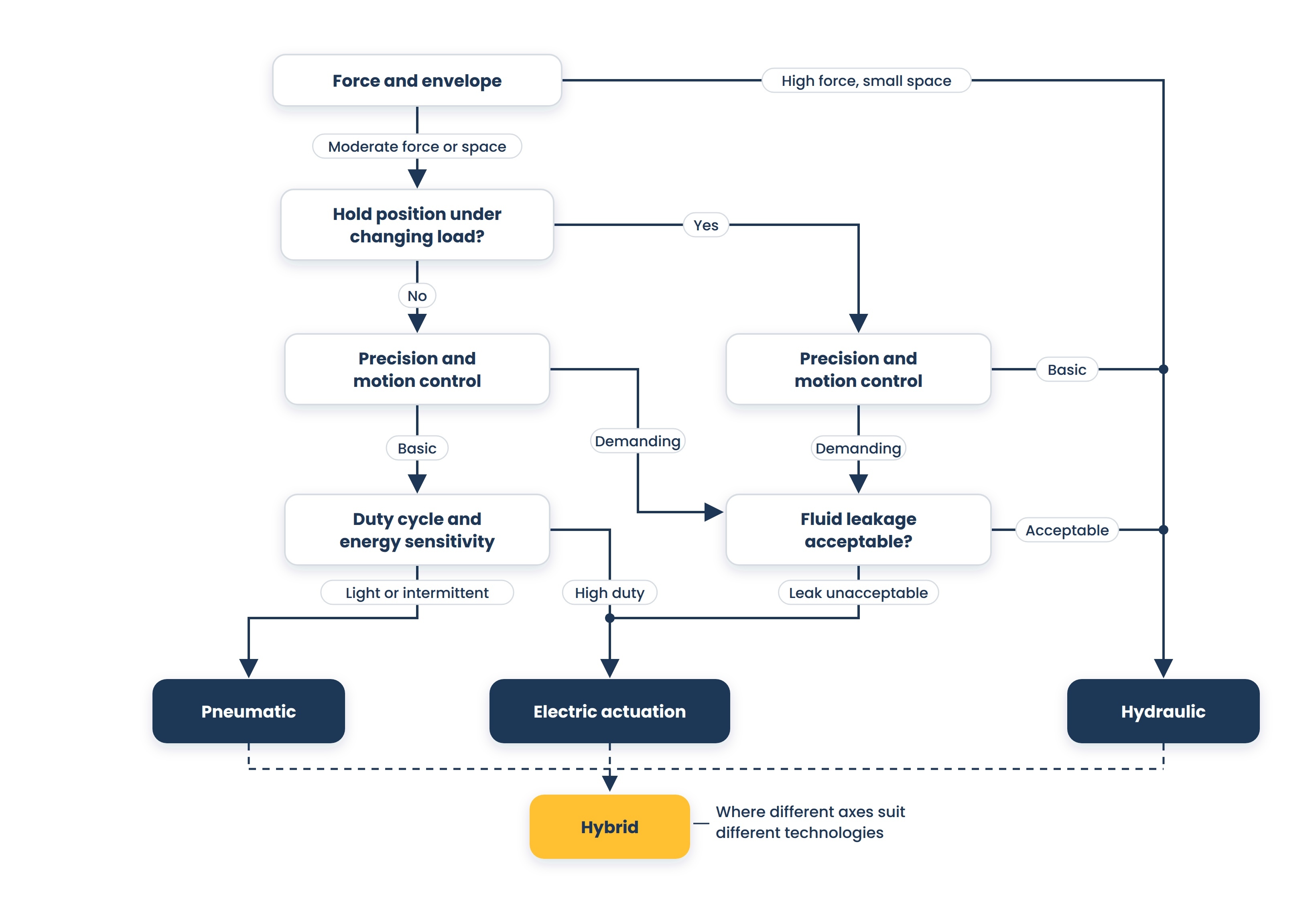
05. The decision path
In this order, the questions narrow the field. Where an answer is unknown, that is the work to do rather than an assumption to make.
- What force or torque is required, and what space is available? If the force is high and the envelope is small, hydraulics are the leading candidate, and most of the remaining questions concern how to support them.
- Does the actuator have to hold or control an intermediate position, and does the load change while it does? If yes, air is unsuitable without additional hardware; the choice is between hydraulic and electric.
- What position and velocity accuracy is required, and does the motion profile need to be controlled rather than just bounded? Demanding control points toward electric or toward proportional hydraulics.
- Would a leak of the working medium be unacceptable? If yes, hydraulics carry a real constraint that may be solvable with fluid selection or may not.
- What is the duty cycle and running hours, and does energy cost matter at that duty? A high duty cycle substantially amplifies the disadvantage in pneumatic running costs.
- What infrastructure already exists, and what would the alternative cost to install? Quantify it rather than letting it decide.
- What must happen on loss of power or loss of supply? A load that can fall, drift, or run away needs that behavior built in, and the answer differs across technologies.
- What is the environment, and what maintenance capability exists on site?
- Has an electric actuator been evaluated for this duty, and if it was ruled out, on what basis?
06. Where each option is the wrong answer
Where hydraulic is wrong
- A single actuator on a machine with no existing hydraulics, where the power unit overhead exceeds the value of the hydraulic advantage.
- Environments where an oil leak would be a contamination, hygiene, or fire problem that fluid selection cannot resolve.
- Operations without the maintenance discipline the technology requires, since a poorly maintained hydraulic system underperforms a well-maintained pneumatic one.
- Very high-cycle-rate simple motion, where the technology is more about the system than the duty needs.
- Applications where the heat generated cannot be rejected, or where the noise of a power unit is unacceptable.
Where pneumatic is wrong
- Any requirement to hold or control an intermediate position under changing load, which is the type's defining limitation.
- High force requirements, where achieving them means an impractically large bore and a large air consumption.
- High-duty-cycle continuous operation, where the running-cost disadvantage compounds every hour.
- Applications requiring accurate, repeatable speed control through the stroke rather than at the ends.
- Situations where the air system is already at capacity, since adding load can degrade service for other users on the network.
- Duty where a load must be held safely without power, unless that is specifically designed in.
Where both are wrong
Where the duty is controlled positioning of a moderate load, particularly at moderate cycle rates, an electric actuator frequently outperforms both in energy, control, and diagnostics. Ruling it out by habit is the most common error in this category. It is worth including in the comparison and worth explaining why it was rejected.
Where the technology is not the problem
If an existing system is underperforming, the cause is frequently not the choice of technology. A hydraulic system that has become slow and hot is usually contaminated, running degraded fluid, or losing energy across a relief valve nobody has looked at. A pneumatic system that has become weak is usually starved by leakage elsewhere on the network, or by pressure drop through undersized pipework and fittings, or by a treatment problem. Before changing technology, measure the actual pressure at the actuator, the available flow, and the fluid or air conditions, because a new system fed by the same infrastructure will disappoint in the same way. Where the symptom is a pneumatic actuator that is weak or slow only at peak demand, the remedy is usually a local receiver or larger feed pipework rather than more compressor, as set out in section 03.
07. Cleanliness and running cost, the two things that decide what it costs to own
Hydraulic fluid cleanliness
The majority of hydraulic component failures are attributed to contamination, and this is the single most useful thing a buyer can understand about the technology. Fluid carries particles through every close-fitting clearance in the system, where they cause wear, generating more particles that accelerate the wear process. It is a self-reinforcing process, and once established, it is expensive to reverse.
Cleanliness is expressed as a code under ISO 4406, published by the International Organization for Standardization, which reports the number of particles above defined sizes in a sample as a set of size ranges. Component manufacturers publish recommended cleanliness levels for their products, and those recommendations differ substantially between component types: a proportional or servo valve, with fine clearances and high control demands, calls for a considerably cleaner system than a gear pump in the same circuit.
That difference is the decision. The system target is set by the most contamination-sensitive component in it, not by an average, and specifying a target without identifying which component drove it is how a servo valve ends up in a circuit filtered for a gear pump. Establish the target, state which component it follows from, and require a filtration arrangement designed to achieve and hold it rather than a filter selected because it fits the port.
- Establish the cleanliness target for the system based on its most contamination-sensitive component.
- Establish the filtration arrangement, its rated efficiency at the particle sizes that matter, where the filters sit, and how filter condition is indicated.
- Establish how new fluid enters the system, since new oil delivered in a drum is routinely dirtier than the system target and filling without filtration undoes the design in one operation.
- Establish the sampling regime: where samples are taken, how often, by whom, and what the trigger levels for action are.
- Establish contamination control during maintenance, since opening a system to change a component is the highest-risk moment for ingress.
- Establish reservoir breathing, since a reservoir that inhales unfiltered workshop air through a plain breather continuously contaminates itself.
- Water contamination is as damaging as particulate contamination and less visible. Water degrades the fluid, promotes corrosion, reduces the lubricating film strength, and enters the reservoir via the breather, seals, and new fluid. Establish how water is excluded, how it is detected, and what the action level is.
- Entrained air, which causes cavitation damage at the pump, accelerates thermal degradation of the fluid, and softens the system in the way described in section 02. Air enters through suction line leaks, low fluid level, and poor reservoir design, and a system that has become noisy or spongy is frequently carrying air rather than failing mechanically.
Compressed air quality
The pneumatic equivalent is air quality, and the classes are defined in ISO 8573-1, published by the International Organization for Standardization, which classifies compressed air purity by particulate, water, and oil content, each expressed as a class. Specifying air quality means stating a class for each of the three, since a system can be clean of particulate and wet, or dry and carrying oil. What treatment your system needs depends on what the air touches: general actuation tolerates a great deal, instrumentation and valves less, and any application where air contacts product needs treatment specified against that requirement rather than against the machinery.
Moisture is the most common culprit. Compressed air carries water that condenses as the air cools and expands, and water in a pneumatic system corrodes, washes out lubricant, and destroys valves. Establish the drying requirement against the coldest point the air reaches, rather than in the compressor room.
The running cost comparison
Both technologies convert electrical energy into mechanical work with substantial losses. Neither is efficient in absolute terms, and comparing them fairly means looking at where the losses occur.
Compressed air loses energy during compression, where much of the input is converted to heat, and again through treatment, distribution pressure drop, leakage, and the actuator. That accumulation is why compressed air is an expensive utility per unit of work, and why leakage matters so much: a leak is a continuous, invisible payment.
Hydraulic systems lose energy through relief valves, throttling, in-line losses, and internal leakage, and these losses depend heavily on the design. A system where flow is throttled to control speed while the pump runs at full pressure wastes a great deal; one with load sensing or variable displacement wastes far less. So hydraulic efficiency is a design decision rather than a property of the technology.
The practical instruction is to request energy consumption at the actual duty cycle as part of the quotation, and to compare total cost over the expected life rather than the installed cost. Ask specifically what happens during idle time, since a compressor cycling to maintain pressure and a power unit running with no demand both cost money when the machine is doing nothing.
08. Safety, standards and what to confirm
The governing standards
The two paired standards are ISO 4413, which specifies general rules and safety requirements for hydraulic fluid power systems and their components, and ISO 4414, which does the same for pneumatic systems. Both are published by the International Organization for Standardization, both work within the general machinery safety framework, and both apply to the design, construction, and modification of systems as well as to individual components, addressing the significant hazards of each technology and the principles for avoiding them.
They cover ground a buyer should recognize: stored energy and its safe release, reservoir and accumulator provisions, contamination control, conductor and connection integrity, and verification before a system is put into service. Related standards address safety-related control functions, connection and port configurations, graphical symbols used on circuit diagrams, and fluid cleanliness and sampling. Where a machine falls under a specific machinery standard, that standard can add to or modify these requirements.
Stored energy is the hazard to design for
Both technologies store energy that persists after the machine is switched off, and this is the safety point that matters most to a buyer.
- Hydraulic accumulators hold substantial energy at pressure and remain charged after shutdown. Isolation, controlled discharge, and clear identification are design requirements, and an accumulator that cannot be safely discharged before maintenance is a design defect rather than a procedural gap.
- Air receivers and the distribution network store energy in the same way, and a pneumatic actuator can move unexpectedly when the supply is restored or when a valve is operated during maintenance.
- Suspended and gravity loads do not hold themselves. Establish what happens to the load when power or supply is lost, and whether a mechanical means of holding it is required rather than relying on a valve.
- Explicitly establish the isolation and energy-dissipation arrangement, including how a technician verifies that the system is at zero energy before working on it.
- For hydraulics specifically, fluid injection injury from a pinhole leak is a serious and poorly known hazard, and it is a reason hose condition, routing, and guarding belong in the specification.
Connections, hoses, and what they commit you to
Hose assemblies and connectors are the most common source of leaks and unplanned downtime in both technologies, and the decisions that determine that are made at purchase.
- Thread and port standards are not interchangeable, and a plant that accumulates several across its machines has a permanent spares problem and a problem at two in the morning. Specify the connection standard at inquiry to match what you already run. It costs nothing at that point, and it cannot be corrected later without changing every fitting.
- Hose assemblies have a service life and are consumables rather than fittings. Establish the expected life, the replacement interval, and whether assemblies are a standard length and specification you can source locally or made to order.
- Routing and bend radius requirements, since a hose bent tighter than its minimum radius or rubbing against structure fails early, and both are installation decisions visible at design review.
- Whether the machine builder will supply hose assemblies to a recognized standard with traceable markings, so that a replacement can be specified from the failed part rather than from a drawing nobody can find.
Component lock-in
Ask at inquiry what you will be able to buy from someone other than the machine builder in five years.
- Whether the valve arrangement uses a standard mounting interface or a custom manifold block, since the first can be replaced from stock and the second cannot.
- Whether proportional or servo valves carry manufacturer-specific electronics or calibration, and whether a replacement can be obtained and configured without the original builder.
- Whether seal kits, cartridges, and cylinder repair parts are available from the component manufacturer or only through the machine builder.
- What is proprietary in the control system, and whether you can obtain parameters and diagnostics without a service visit.
Take This to Your Next Conversation
Fifteen questions drawn from this guide. The answers together will usually settle the technology and expose any assumption you did not make yourself.
- What force and speed does this deliver at the actuator under my actual load, rather than at the supply?
- Does my application need to hold or control an intermediate position, and does the load change while it does?
- Can my existing infrastructure deliver the pressure and flow this needs while also serving everything else it supports?
- For hydraulics: what cleanliness target is this designed to, and what filtration arrangement holds it?
- How does clean fluid get into the system at fill and top-up, and how is it sampled afterward?
- For hydraulics: how much heat does this generate at my duty cycle, and what rejects it?
- For pneumatics: what is the air consumption at my duty cycle, and what air quality do these components require?
- What is the energy consumption at my duty cycle, and what does the system draw while the machine is idle?
- What happens to each axis on loss of power and on loss of supply, and what holds a suspended load?
- Where is energy stored after shutdown, how is it isolated and discharged, and how does a technician verify zero energy?
- Which standards is this designed to meet, and does a machinery-specific standard add anything?
- What maintenance does this require, at what interval, and what skills does it assume?
- Was an electric actuator evaluated for this duty, and if it was rejected, on what basis?
- If I compare the total cost over 10 years, including energy, rather than the installed cost, does the answer change?
- What have you seen fail in applications like mine, and what changed as a result?
About this guide
Written by the Industrial Web Search editorial team. This guidance is general and does not replace engineering design for a specific machine or installation. The standards referenced here are revised periodically, and their current editions are the authority; machinery-specific standards can supplement or modify the general requirements described. Energy consumption, efficiency, and leakage vary widely with system design, duty cycle, and maintenance, so comparisons should be made against your own duty rather than general figures. Safety requirements, including stored-energy isolation, load holding, and machinery safety obligations, depend on the machine and the jurisdiction. Confirm design, safety, and regulatory requirements with a qualified engineer for your application.