The Short Version
- A shielding effectiveness figure is meaningless without the frequency, the field type and the test method that produced it. The same material can be quoted at very different numbers by three suppliers who all measured honestly.
- Test methods are not interchangeable. Planar material tests measure a flat sheet under far-field conditions and do not apply to cables or connectors. Enclosure tests measure a built assembly and have a minimum size. A material figure is not an enclosure figure.
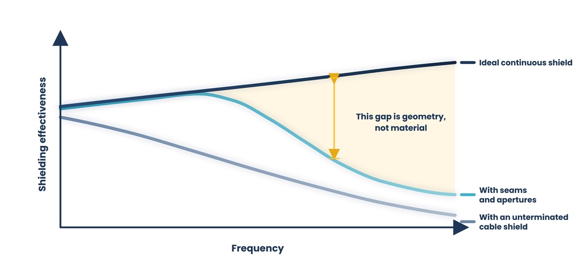
- Openings dominate. A well-chosen material with a poorly closed seam performs worse than a modest material with a well-closed one, and leakage through a slot depends on its longest dimension rather than its area.
- Low-frequency magnetic fields are a different problem from everything else. Conductivity does not solve them; they require high-permeability material, distance, or source control.
- A gasket must maintain continuous low-resistance contact along the entire joint, which makes closure force, deflection range, joint stiffness, and fastener spacing part of the shielding specification rather than mechanical details.
- Galvanic compatibility between the gasket and the housing determines whether the joint still works in three years. A corroded interface is a resistive interface, and a resistive interface is a leak.
- Cables are the most common leakage path in an otherwise sound enclosure, because a shield terminated by a short pigtail stops behaving like a shield at higher frequencies.
EMI shielding gets specified backward more consistently than almost anything else in industrial procurement. A number is chosen, usually a decibel figure someone found in a datasheet, and materials are compared against it. The enclosure is built, it fails a compliance test, and the response is to look for a better material, even though the material was never the limiting factor.
The reason is that a shield is a system, not a component. Its performance is set by the weakest path through it, and those paths are almost always the openings: seams, doors, panels, ventilation, displays, and above all the cables passing in and out. What follows works through the specification in the order it should be decided, starting with defining the problem, because a shielding requirement stated without a frequency and a field type cannot be engineered against or quoted against.
01. Define the problem before selecting anything
Eight questions define the requirement. A supplier cannot answer any of them for you, and a recommendation made without them is a guess.
- Are you keeping energy in, keeping it out, or both? Emissions and immunity are distinct problems and may require different measures within the same enclosure.
- What frequencies matter? Not the whole spectrum, but the specific ranges where the source emits or the victim is sensitive. This single answer eliminates more wrong approaches than any other.
- Is the problem an electric field, a magnetic field, or a plane wave? At low frequency, these behave very differently and require different materials. At higher frequency, the distinction matters less.
- How far is the source from the shield, relative to the wavelengths involved? Close to a source, the field behaves differently from the way it behaves at a distance, and shielding that works well in one case can perform poorly in the other.
- What performance is required, expressed as attenuation across the specific frequency ranges rather than as a single figure?
- What compliance regime applies, and what does it actually require? The enclosure serves a compliance obligation rather than an abstract target, and its limits are set by the applicable standard.
- What does the enclosure have to do besides shield: thermal management, ingress protection, access for service, display visibility, weight, and cost.
- What are the expected service life and environment, since a joint that works at build but degrades over three years has not solved the problem?
A note on the second and third points. Buyers frequently arrive with a requirement expressed as a single number across a wide band, because that is how datasheets present performance. Converting it into required attenuation at specific frequencies is the work that makes the rest of the specification possible, and it is usually the difference between an enclosure that passes and one that is expensive and still fails.
02. What attenuation figures actually mean
Shielding effectiveness is a ratio, not a property
Shielding effectiveness expresses the reduction in field strength produced by the shield, in decibels. Because it is logarithmic, each additional ten decibels represents another factor of roughly three in field strength, and every twenty decibels a factor of ten. That scaling is worth holding on to because the difference between the two quoted figures is larger than the arithmetic gap suggests.
The important point is that shielding effectiveness is not a fixed property of a material. It is the result of a particular material, in a particular thickness, in a particular geometry, at a particular frequency, against a particular field type, measured by a particular method. Change any of those and the number changes. Two suppliers can quote very different figures for comparable products and both be reporting accurately.
The three mechanisms
A shield works by reflecting energy at its surface, by absorbing energy as it passes through, and by a correction term for energy that reflects back and forth inside a thin shield. Reflection depends mostly on conductivity and dominates at lower frequencies for electric fields. Absorption depends on conductivity, permeability and thickness, and becomes more significant as frequency rises. Understanding which mechanism is doing the work matters because it tells you which material property to specify: conductivity for reflection, permeability and thickness for absorption of magnetic fields.
Why low-frequency magnetic fields are the hard case
At low frequencies, magnetic fields pass through good conductors that would easily block electric fields. Reflection is weak because the wave impedance is low, and absorption requires either substantial thickness or high-permeability material. This is why the usual answers to a low-frequency magnetic problem are not better conductive shielding but high-permeability alloys, increasing the distance between source and victim, reorienting the source, or reducing the loop area that creates the field in the first place. A buyer whose problem is a nearby transformer or motor drive operating at power frequencies should be told this early, because a conductive enclosure will not solve the problem.
How to state a requirement
State required attenuation as a set of values against frequency bands, with the field type identified where it matters, and name the test method the figure will be verified against. A requirement written that way can be engineered against, quoted against and tested against. A single decibel figure across a wide band cannot, and it invites suppliers to quote whichever test makes their product look best.
03. Material selection
What the choice depends on
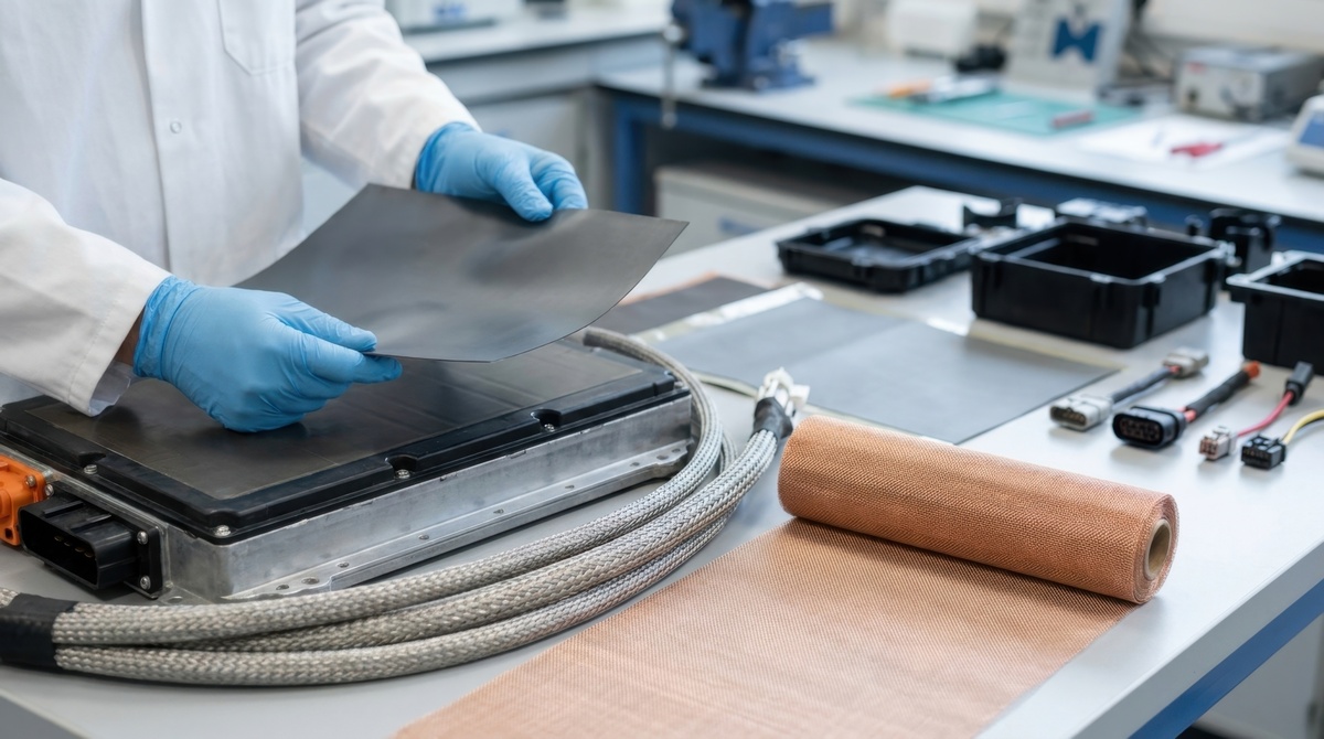
Material follows from the frequency range, the field type, and the mechanism doing the work, and it is constrained by everything the enclosure must also be: manufacturable, formable, finishable, corrosion-resistant, and appropriate in weight and cost.
- Copper offers high conductivity and is the usual reference point for reflective shielding, though at a cost and with added weight.
- Aluminum offers good electrical conductivity and a much lower weight, and is widely used for enclosures, but its oxide is non-conductive, which makes surface treatment at joints a design requirement rather than an option.
- Steel is less conductive than copper or aluminum but has significant permeability, which makes it more effective than its conductivity alone would suggest at lower frequencies and in magnetic fields.
- High-permeability nickel-iron alloys are the specific answer to low-frequency magnetic fields, and they behave differently from ordinary structural materials: their permeability depends on the annealed state, and forming, machining, or bending after annealing degrades it; therefore, parts are frequently annealed after fabrication.
- Conductive coatings applied to plastic housings turn a non-conductive enclosure into a shielding one. Performance depends on coating thickness, adhesion and continuity, and on the coating's ability to withstand handling and thermal cycling. Coverage at edges and around openings is where these systems usually fall short.
- Conductive plastics and filled composites integrate shielding into the molded part, generally with lower effectiveness than metal but with the advantage that geometry and shielding are produced in a single operation.
- Absorbing materials work differently: rather than reflecting energy, they dissipate it, which suits cavity-resonance problems and situations where reflection inside an enclosure is the difficulty.
Thickness and skin depth
Energy at higher frequencies travels near the surface of a conductor, and the depth at which it becomes significantly attenuated falls as frequency rises. The practical consequences are that, at higher frequencies, quite thin material shields effectively, so a thicker enclosure buys little additional attenuation; and that, at lower frequencies, particularly for magnetic fields, thickness genuinely matters. This is another reason the frequency range must be determined before material is chosen.
04. Apertures and seams: where shields actually leak
The dominant factor
A continuous, unbroken conductive enclosure is an excellent shield. Real enclosures have lids, doors, panels, ventilation, displays, indicators, controls, and cable entries, and each one interrupts the conductive surface. Energy leaks through those interruptions, and above the frequencies where they become significant relative to the wavelength, they completely dominate performance.
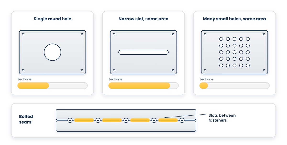
The critical dimension is the longest dimension of the opening, not its area. A long narrow slot leaks far more than a round hole of the same area, because it behaves as an efficient radiating structure at the frequencies whose wavelength relates to its length. This is the single most useful thing a buyer can understand about shielding geometry, and it explains most of the design guidance that follows.
What follows from it
- Many small openings outperform a single large opening with the same total area, which is why ventilation is provided using perforated patterns or honeycomb panels rather than cutouts.
- Honeycomb vent panels work because each cell behaves as a waveguide below its cutoff frequency, attenuating strongly while passing air. Cell size and depth determine the frequency above which they stop working.
- A bolted seam is electrically equivalent to a series of slots between the fasteners, so fastener spacing is a shielding parameter. Reducing spacing or adding a gasket that maintains continuous contact addresses it.
- Displays and windows need conductive treatment: fine wire mesh laminated into the window, or a transparent conductive coating, each trading optical clarity against attenuation.
- Every shaft, control, indicator, and mounting hole that passes through the shield is an opening and should be treated as such.
Grounding and bonding
The purpose of bonding across a joint is to make the two sides electrically continuous at the frequencies of concern, which is a question of impedance rather than of direct current resistance. A joint can measure a very low resistance with a meter and still perform poorly at high frequency if the bond path is long or inductive. Short, wide, direct bonds work; long thin straps behave as inductors. This is why a shielding specification concerns itself with how joints are made rather than only with what they are made of.
05. Gaskets
What a gasket has to do
An EMI gasket makes continuous electrical contact along a joint, closing the slot that the joint would otherwise present. That is a different job from an environmental seal, though many gaskets are asked to do both. Where a joint must exclude water and close electrically, the interaction between those two requirements has to be worked out rather than assumed.

The main families
- Knitted wire mesh, which conforms well and tolerates high closure forces, is used where robustness matters more than a low closure force.
- Beryllium copper fingerstock, which provides high contact pressure at many discrete points, tolerates repeated opening and closing, and suits doors and removable panels. It requires a defined deflection range and can be damaged by over-compression.
- Conductive elastomers, which combine a polymer matrix with conductive filler to provide both electrical continuity and environmental sealing in one component. The filler choice affects both conductivity and galvanic behavior.
- Oriented wire in elastomer, where wires held in a carrier provide the conductive path through the joint while the elastomer provides sealing and compliance.
- Conductive fabric over foam, which achieves good performance at low closure force, suited to lightweight enclosures and consumer-scale hardware where high clamping force is not available.
The specification points buyers miss
- Closure force available. A gasket that requires more compression than the enclosure and its fasteners can provide will not make continuous contact, and the enclosure will underperform for reasons that appear to be a material problem.
- Deflection range: the minimum compression required to work and the maximum before the gasket is damaged. Both matter, and a design that bottoms out on metal before compressing the gasket has no gasket.
- Joint stiffness and flatness. A stiff flange holds compression evenly; a thin panel bows between fasteners, and the gasket in the bowed region is not compressed. This is why fastener spacing and flange stiffness appear in shielding calculations.
- Compression set refers to how much compression the gasket permanently loses over time and temperature, which determines whether the joint still closes electrically after years in service.
- Number of open and close cycles the joint will see, since gaskets differ enormously in how many they tolerate.
- The surface the gasket contacts. Paint, anodizing, and oxide layers are insulators, so contact areas need masking, conductive finishes, or a treatment that remains conductive.
06. Galvanic compatibility, and why joints fail in service
Two dissimilar metals in electrical contact, in the presence of moisture, form a galvanic cell and the less noble one corrodes. In a shielded joint, this matters more than in most mechanical assemblies, because the product of that corrosion is usually a poorly conductive layer, and a resistive joint is an electrical opening. The enclosure that passed testing at build quietly degrades.
The mitigations are ordinary and effective, provided they are specified. Choose a gasket whose contact material is galvanically close to the housing material. Use platings and conversion coatings that remain conductive while improving compatibility. Exclude moisture from the joint where the environment allows. And where an incompatible pairing cannot be avoided, say so explicitly so that the service life expectation is realistic rather than assumed.
This is worth raising directly with a supplier, because compatibility depends on the specific pairing of housing finish and gasket filler rather than on the gasket alone. A gasket that suits an aluminum housing may be a poor choice for a stainless one, and the supplier will know which pairings cause them problems if asked.
07. Cables, connectors and filtering
An otherwise sound enclosure most often leaks through what passes into it. A conductor entering a shielded volume carries energy across the boundary directly, and unless it is treated at the point of entry, the shield around it is largely irrelevant.
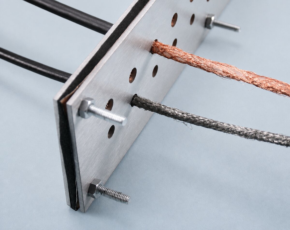
- Terminate cable shields at the enclosure point of entry, around their full circumference. A shield gathered into a short wire and connected at a single point behaves as an inductor at higher frequencies and stops functioning as a shield, which is a common and quietly expensive mistake.
- Use connectors with conductive backshells and gaskets designed to maintain continuity from the cable shield through the connector body to the enclosure wall.
- Filter conductors that cannot be shielded, particularly power and low-frequency signal lines, at the point where they cross the shield boundary rather than somewhere convenient inside it.
- Treat the enclosure boundary as a defined surface and require that every penetration be treated at that surface; this is a design rule rather than a component choice.
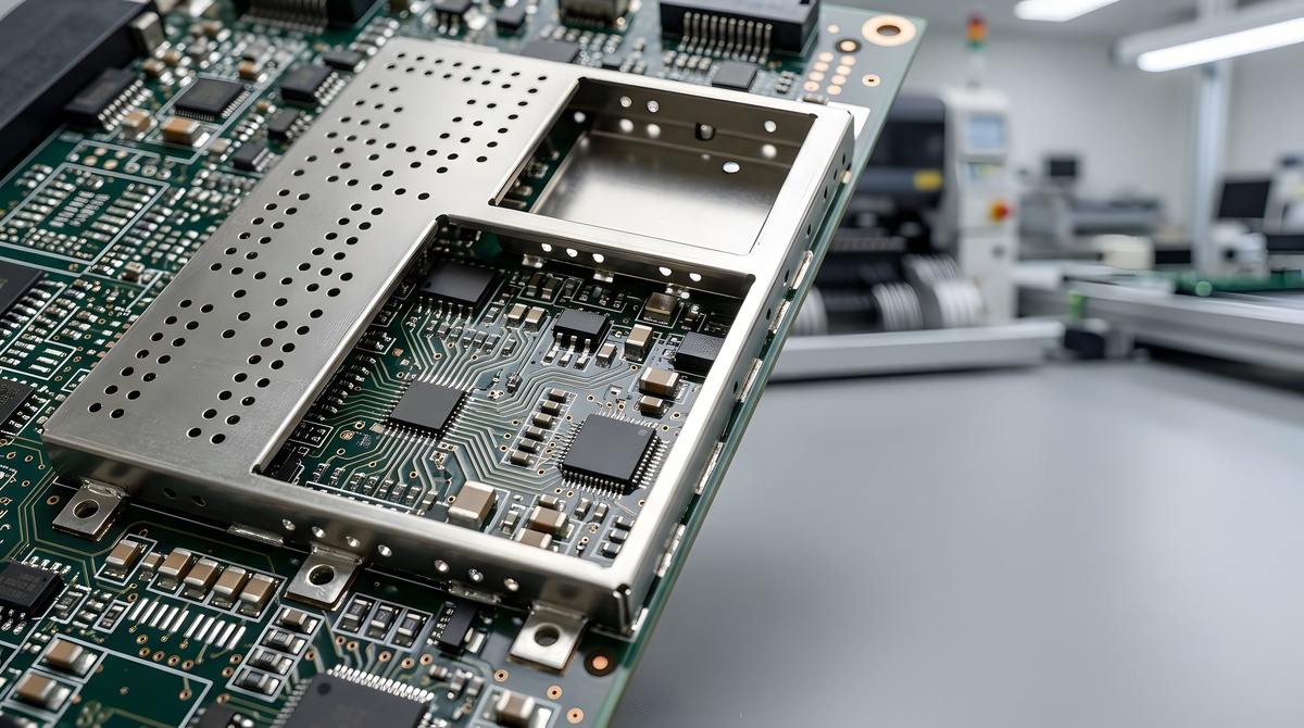
- Consider board-level shielding, where a source or victim can be enclosed locally, since a small shield close to the problem often outperforms a large one far from it and removes the need for an outer enclosure.
08. Testing: what the standards actually measure
The methods are not interchangeable
Several recognized methods exist for measuring shielding effectiveness, each measuring different aspects. Quoting a figure without naming the method is the source of most confusion in this category.
- ASTM D4935, published by ASTM International, is the standard test method for measuring the electromagnetic shielding effectiveness of planar materials. It applies under normal-incidence far-field plane-wave conditions, using a coaxial specimen holder, over a defined frequency range bounded at the low end by reducing capacitive coupling and at the high end by exciting modes other than the intended one for the holder size. The standard states explicitly that it is not applicable to cables or connectors. It is the benchmark for comparing sheets, foils, fabrics and composites, and it characterizes a material rather than a product.
- IEEE 299, published by the Institute of Electrical and Electronics Engineers, defines uniform procedures for measuring the effectiveness of electromagnetic shielding enclosures over a wide frequency range, for enclosures above a defined minimum size. A companion standard addresses smaller enclosures. These measure a built assembly, including its seams, apertures, and penetrations, which actually determine performance.
- A dedicated military specification covers conductive elastomer gasketing material, including how its shielding effectiveness is measured, and serves as the reference for comparing elastomeric gaskets.
- Military standards for the control of electromagnetic interference characteristics of equipment define emissions and susceptibility limits, along with the test methods for demonstrating them, which is a different question from measuring the shielding of a material or an enclosure.
- Commercial compliance regimes define emissions and immunity limits for equipment placed on the market, and these differ by market and by product category. The enclosure exists to help meet those limits, so the applicable regime should be identified before the shielding target is set.
What this means when comparing suppliers
A material figure and an enclosure figure are not comparable, and neither predicts the other. When a supplier quotes attenuation, establish which method produced it, at which frequencies, on what specimen or assembly, and whether the test was performed by an accredited laboratory. Where the numbers from two suppliers differ substantially, the explanation is frequently the method rather than the product.
Verify the assembly, not just the parts
Because performance is set by openings and joints, the only test that answers the real question is one performed on the assembled enclosure in a configuration representative of how it will be built and closed, including cables. Plan for that verification rather than assuming that specifying good components produces a good enclosure. Where a design is new, or the requirement is demanding, testing a representative prototype before committing to production tooling is far cheaper than discovering the problem at compliance testing.
09. What to send a supplier
A supplier asked for shielding without the following is guessing. The package below allows a competent supplier to propose a specific approach and lets several be compared on the same basis.
The requirement
- Whether the concern is emissions, immunity or both, and what is being protected from what.
- Required attenuation stated against specific frequency bands, with the field type identified where it matters, rather than as a single figure.
- The compliance regime and the specific standard the equipment must satisfy, and the market it will be sold into.
- Known or suspected sources and their frequencies, and the distance between source and shield.
The enclosure
- Drawings or a model of the enclosure, showing every seam, joint, opening, penetration and fastener location.
- Housing material and its surface finish at the joints, specifically, since the finish, rather than the base material, is what a gasket contacts.
- Closure arrangement: fastener type and spacing, flange width and stiffness, and the closure force actually available.
- How often the enclosure will be opened in service, and by whom.
- Ventilation and thermal requirements, display and control openings, and ingress protection requirements.
The environment and the life
- Operating and storage environment, including temperature range, humidity, salt or industrial atmosphere and any chemical exposure.
- Expected service life, and whether performance must be maintained across it or only demonstrated at build.
- Vibration and mechanical duty, which affect gasket retention and joint integrity.
Cables and verification
- Every conductor entering the enclosure, with its function, and whether it can be shielded, filtered or neither.
- Connector types are already selected, since they constrain which terminations are possible.
- What testing is planned, to which method, by whom, and at what stage of the program.
One further note on how to ask. A supplier who responds by asking about your frequencies, closure force, and housing finish is engaging with the problem. One who responds with a material datasheet and a decibel figure has not done so, and the difference will not be visible until the enclosure is tested.
Take This to Your Next Conversation
Fifteen questions drawn from this guide. Taken together, the answers will tell you whether a supplier is solving your problem or selling a material.
- What attenuation does this deliver at my specific frequencies, rather than as a single figure across a band?
- Which test method produced that number, and was it a material test or an enclosure test?
- Was the test performed on a flat specimen, or on an assembly with seams and openings like mine?
- Was it performed by an accredited laboratory, and can I see the report?
- If my problem is a low-frequency magnetic field, is conductive shielding the right approach at all?
- What closure force does this gasket need, and does my enclosure and fastener arrangement deliver it?
- What is the working deflection range, and what happens if the joint over-compresses or bottoms out on metal?
- What compression set should I expect over my service life and temperature range?
- Is this gasket galvanically compatible with my housing material and its surface finish at the joint?
- What surface preparation or masking does my housing need where the gasket contacts it?
- Given my fastener spacing and flange stiffness, will the compression be uniform throughout the joint?
- How should the cable shields and connectors at my penetrations be terminated?
- Which openings in my enclosure do you expect to be the limiting leakage path?
- What would you change about the enclosure design to improve performance before changing the material?
- What have you seen fail in applications like mine, and what changed as a result?
About this guide
Written by the Industrial Web Search editorial team. This guidance is general and does not replace electromagnetic compatibility engineering for a specific product. The test methods and standards referenced here are revised periodically, and their current editions are the authority; they measure different things and are not interchangeable. Emissions and immunity requirements vary by market and by product category and are revised on their own schedules. Verify every specification against the current edition of the governing standard and against manufacturer documentation for the specific product, and confirm applicable compliance obligations for your equipment and market with a qualified engineer.