The Short Version
- A centrifugal pump adds energy to a fluid and lets the system decide how much flows. A positive displacement pump moves a fixed volume per revolution and lets the system decide what pressure that takes. Flow control, protection, and failure behavior all follow from that difference.
- A positive displacement pump discharging into a closed valve will raise pressure until something fails, which is why pressure relief is a safety requirement rather than an option on these installations.
- Viscosity separates the two families more sharply than anything else. Centrifugal performance falls away as viscosity rises. Positive displacement pumps generally handle viscous fluids well, and some perform better with them.
- Centrifugal flow varies with system pressure, so controlled flow requires a drive, a flowmeter, and a tuned loop working together. A positive displacement pump delivers near-constant flow as pressure changes, which is what makes dosing and precise metering practical.
- A centrifugal pump has one flow rate at which it runs best. Operating far from it reduces efficiency and shortens life due to mechanical loading, which is why both the duty point and the actual operating range must be stated.
- Shear matters. A centrifugal impeller works fluid hard, which damages emulsions, suspensions, and long-chain products. Several positive displacement types are chosen specifically for their ability to handle product gently.
Pump selection is often treated as a sizing exercise: establish the flow and the head, and pick something that covers both. That works when the fluid is close to water, and the duty is steady, which is why it often becomes a habit. It stops working as soon as the fluid is viscous or shear-sensitive, the flow has to be accurate, or the system pressure varies, and at that point the habit produces a pump that runs but does not do the job.
The two families are built on different principles. One adds velocity to a fluid, converting it to pressure; how much flows depends on what the system does with that pressure. The other captures a fixed volume and pushes it along, with the pressure set to whatever it takes to move it. What follows describes each on its own terms, including what it costs you, then gives the decision path in the order the questions should be asked. Neither is better. Each wins under conditions that can be stated plainly, and most of those conditions are properties of the fluid rather than of the pump.
01. What actually decides this
Nine variables drive the choice. The first three usually settle it.
- The fluid: viscosity across the full temperature range it will see, density, vapor pressure, solids content and particle size, abrasiveness, corrosiveness, and whether it is shear sensitive.
- Whether flow accuracy matters. Metering, dosing, and blending require flow that does not change with system pressure, which eliminates the centrifugal family for that duty.
- The pressure the system requires, and whether it varies. A system whose resistance changes substantially during operation behaves very differently under the two families.
- Flow rate, and whether it is constant or must be varied, and by how much.
- Suction conditions: the level and pressure at the source, the losses between the source and the pump, and the fluid's vapor pressure, which together determine the available suction head.
- Duty cycle: continuous, intermittent, or frequent starting and stopping.
- Whether the pump must self-prime, run dry briefly, or handle entrained gas.
- Hygiene, containment, and cleaning requirements, which constrain construction and sealing before hydraulics is considered.
- The governing standard, the owner's specification, and what the plant already runs and can maintain.
The fluid is first for a reason. Flow and head can be met by many pumps. Viscosity, shear sensitivity and solids narrow the field to a handful, and they do it before any curve is consulted.
02. Centrifugal
What it is
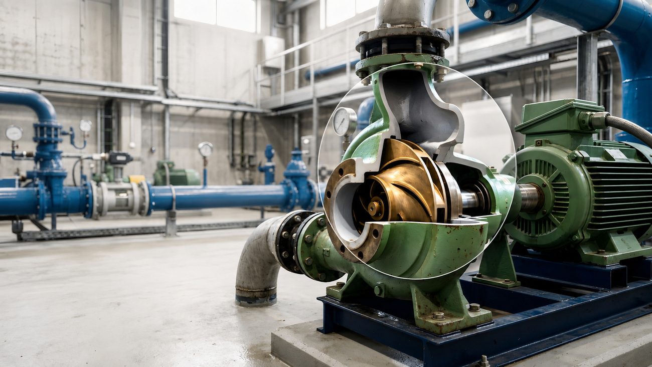
A rotating impeller accelerates fluid outward, and the casing converts that velocity into pressure. There is no sealed volume moving through the pump, so fluid can flow back through the clearances if the discharge pressure is high enough. That is why flow falls as pressure rises, and why the pump has a maximum pressure it can develop at all, reached when flow drops to zero.
The consequence is a performance curve rather than a performance point. Where the pump actually operates is set by where its curve crosses the system curve, and the system curve belongs to your piping, not to the pump.
What it suits
- High flow at moderate pressure, which is the bulk of industrial and utility pumping duty.
- Low-viscosity fluids, particularly water and water-like liquids.
- Continuous, steady-state service where the operating point does not move much.
- Applications where flow does not need to be accurate, and where variation with system pressure is acceptable or even useful.
- Duties where simplicity and low maintenance matter, since there are few close-fitting moving parts.
- Systems where a closed discharge valve must not produce destructive pressure. A centrifugal pump reaches its shutoff head and stops delivering rather than continuing to build up pressure, though that is protection against overpressure and not permission to deadhead it, as the following section explains.
- Fluids with modest solids, using impeller designs intended for them.
What it costs you
Viscosity is the clearest limit. As viscosity rises, more energy is lost to friction inside the pump; the developed head, flow, and efficiency fall accordingly. Performance corrections exist and are applied by suppliers, but they represent a penalty rather than a removal, and beyond a certain point, the centrifugal family stops being the right answer.
Flow is not controllable in the sense that a metering application needs. It depends on the system, so any change in resistance, a fouled filter, a throttled valve, or a change in static head moves the flow. Throttling to control flow works and is common, but it wastes energy by design because it adds resistance that pushes the pump back along its curve.
Operating away from the best-efficiency flow costs more than operating efficiently. Off that point, the flow through the impeller becomes less uniform, which loads the shaft radially, and that loading shows up in bearings and seals as reduced life. At very low flow, recirculation inside the pump and rising temperature become concerns, which is why a minimum continuous flow is specified and why running a centrifugal pump against a nearly closed valve for long periods damages it, even though it survives the pressure.
Suction conditions bite here more than most buyers expect. A centrifugal impeller creates a low-pressure region at its eye, and if the local pressure falls below the fluid's vapor pressure, vapor bubbles form and collapse violently as they move to higher pressure. That is cavitation, and it erodes the impeller, makes noise and vibration, and destroys performance.
Finally, a centrifugal pump works the fluid. For emulsions, suspensions, biological products, and long-chain polymers, that shear can degrade the product itself, which is a quality problem no amount of hydraulic performance compensates for.
One caution about the shutoff behavior above. A centrifugal pump held against a closed valve does not overpressurize the system, but it does continue to deliver energy to a liquid that is no longer moving. As the liquid heats, depending on the fluid, it can flash, destroying the seal and then the bearings. The pump withstands the pressure and fails due to heat, usually within minutes rather than hours. This is why minimum flow protection exists and why it appears in section 08.
03. Positive displacement
What it is
A positive displacement pump captures a defined volume of fluid and moves it from suction to discharge. Each revolution or stroke delivers approximately that volume, regardless of the pressure the system exerts, so flow remains close to constant while pressure adjusts to whatever the system demands. Close to constant rather than fixed: slip, wear, viscosity, speed, and suction condition all move the delivered figure, as the rest of this section explains. The gap between theoretical and actual delivery is slip: fluid leaking back through internal clearances, which increases with pressure and decreases with viscosity.
The family divides into rotary types, including gear, lobe, screw, vane, progressing cavity and peristaltic designs, and reciprocating types, including piston, plunger and diaphragm designs. They differ in how gently they handle product, how well they tolerate solids, how much pulsation they produce and how accurately they meter.
What it suits
- Viscous fluids, where centrifugal performance collapses, and several positive displacement types actually improve, because higher viscosity reduces internal slip.
- Metering, dosing and blending, where flow must be accurate and repeatable independent of discharge pressure.
- High pressure at low flow, which the centrifugal family serves poorly.
- Shear-sensitive products, using types that move fluid gently rather than accelerating it.
- Systems whose discharge pressure varies, since delivered flow stays near constant while pressure changes.
- Self-priming duty and applications with entrained gas, which many positive displacement types handle far better.
- Hygienic and sanitary services, with several types available in cleanable constructions.
What it costs you
The defining hazard is that the pump does not know how to stop. Discharging into a closed or blocked line, it will continue to displace fluid and raise pressure until something yields: a relief device, if one is fitted, or the pump, the piping, or the seal, if one is not. Overpressure protection is therefore a safety requirement for these installations, and it needs to be sized and located to actually protect the pump rather than just be somewhere convenient.
Close internal clearances are what make the pump work and what make it vulnerable. Abrasive solids wear those clearances, and wear shows up directly as increased slip and lost delivery. Some types tolerate solids well, and those are chosen deliberately for that reason rather than assumed.
Most positive displacement pumps deliver in pulses rather than smoothly, and reciprocating types most of all. Pulsation causes vibration, noise, piping fatigue, and measurement error downstream, and dampening it is part of the system design rather than an accessory.
Maintenance is generally higher. There are more precision-moving parts, and their condition directly determines performance, so wear is not a gradual degradation of efficiency so much as a gradual loss of the specified flow. Running dry is also more damaging to most types than to a centrifugal pump.
Finally, these pumps are usually less economical at high flow and moderate pressure, which is exactly the duty for which the centrifugal family was built.
04. The boundary cases
Three situations sit between the families and are worth knowing before the choice is forced.
Speed control changes the centrifugal argument
Varying pump speed shifts the pump curve, which moves the operating point without adding throttling losses. Because pump power varies with the cube of speed for a fixed system, reducing speed to reduce flow saves substantially more energy than throttling does. Where flow must vary regularly, this narrows the practical gap between a centrifugal pump and its alternatives, though it does not provide flow independent of system pressure.
Regenerative turbine and other intermediates
Some designs sit between the two families, developing higher pressure at low flow than a conventional centrifugal pump while still being rotodynamic. They suit low-flow, high-head duties on clean, low-viscosity fluids, and they are worth considering when a duty falls awkwardly between a multistage centrifugal and a positive-displacement selection.
Multistage centrifugal against positive displacement at high pressure
Where high pressure is needed at reasonable flow on a clean, thin fluid, staging a centrifugal pump often beats a positive-displacement selection in cost, simplicity, and maintenance. The positive displacement case strengthens as flow falls, viscosity rises, or accuracy becomes a requirement. Asking a supplier to quote both is reasonable where the duty is genuinely near the boundary.
05. The decision path
In this order, the questions narrow the field. Where an answer is unknown, that is the work to do, not an assumption to make.
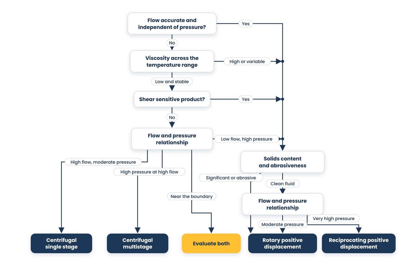
- What is the fluid, and what is its viscosity across the full temperature range including startup? High or variable viscosity points to positive displacement, and the answer at cold start matters as much as at operating temperature.
- Does the flow have to be accurate, and how accurate? Precise dosing, metering, and blending point to the positive displacement family, and the remaining questions concern which type. Where moderate flow control is enough, a centrifugal pump with a drive, a flowmeter, and a tuned loop is a legitimate answer and often a cheaper one.
- Is the product shear sensitive? If yes, that eliminates several options in both families and points toward the gentler positive displacement types.
- What solids are present, at what size, and how abrasive? Solids favor designs with generous clearances or with no close-fitting parts in contact with the fluid.
- What flow and pressure are required, and how do they relate? High flow at moderate pressure favors centrifugal pumps; low flow at high pressure favors positive-displacement pumps.
- Does the system resistance vary during operation, and does flow need to stay constant when it does?
- What suction conditions does the system provide, and is there enough margin over what the pump will require?
- Does the pump need to self-prime, tolerate dry running, or handle entrained gas?
- What can the site maintain, and what protective devices will actually be fitted and tested? If a positive displacement pump is selected, relief protection is part of the answer, not a later purchase.
06. Where each option is the wrong answer
Where centrifugal is wrong
- The fluid is viscous, or its viscosity rises sharply at ambient or startup temperature.
- Flow has to be dosed or metered precisely, since even with closed-loop control the delivered flow moves with system pressure and turndown is limited.
- The duty is low flow at high pressure, where the family is inefficient, and the pump ends up running far from its best point.
- The product is shear sensitive and would be degraded by the impeller.
- System resistance varies significantly, and flow must stay constant.
- The pump must self-prime or handle significant entrained gas without additional equipment.
- The only way to achieve the required flow is to run the pump well away from its best-efficiency point for extended periods.
Where positive displacement is wrong
- The duty is high flow at moderate pressure on a thin fluid, which is centrifugal territory on cost, size and simplicity.
- The fluid carries abrasive solids that will attack the close clearances the pump depends on.
- Downstream equipment or measurement cannot tolerate pulsation and dampening is not being designed in.
- The site cannot support the maintenance the type requires, or dry running is a realistic operational risk.
- The discharge line can be closed by an operator or a control system without the pump being protected.
Where the pump is not the problem
A pump that does not deliver is frequently a system problem wearing a pump costume. A blocked suction strainer, a partly closed valve, air in the suction line, a fouled discharge line raising system resistance, a fluid colder and thicker than the design assumed, or a level lower than the calculation used will all present as a pump that has lost performance. Cavitation, in particular, is almost always a suction-system problem rather than a pump defect. Before replacing anything, measure the actual suction and discharge pressures, actual flow, and fluid temperature, and compare them with the design datasheet, because a new pump in the same system will disappoint in the same way.
07. Suction conditions, curves and sizing
Net positive suction head
Every pump needs the pressure at its suction to stay above the fluid's vapor pressure, or the fluid will boil inside the pump. The margin available is a property of your system: the pressure and level at the source, minus friction losses in the suction line, minus the vapor pressure of the fluid at its actual temperature. The margin the pump requires is a property of the pump and is specified by the manufacturer.
Available must exceed required, and by a margin rather than by a whisker. The reason is in how the required figure is established: published net positive suction head required conventionally corresponds to the point at which cavitation has already begun to measurably degrade head, rather than to the point at which it starts. Operating at the published figure therefore means operating with cavitation present, which is why margin over it is part of the specification rather than optional headroom. Three points are worth holding onto. Vapor pressure rises steeply with temperature, so a hot fluid is a much harder suction problem than the same fluid cold. The required figure varies across the pump's flow range and is usually worst at high flow, so it has to be checked at the actual operating point rather than at the rated one. And the available figure is what your system provides today, which changes as strainers foul and levels fall.
The suction piping, which is where the margin is usually lost
Net positive suction head available is calculated for the system, which is mostly piping. Most suction problems are built into the piping rather than the pump, and they are cheap to prevent but expensive to correct.
- Keep the suction line short, direct, and as free of fittings as the layout allows. Every elbow and valve is friction subtracted from the margin.
- Use eccentric reducers with the flat side up on a horizontal suction, so that air cannot collect in the reducer. A concentric reducer, or an eccentric one fitted upside down, creates a pocket that will hold gas against the pump inlet.
- Establish whether the suction is flooded or a lift. A lift consumes margin before the fluid reaches the pump, making priming and gas-handling design questions rather than operational ones.
- Check submergence at the source. Insufficient depth over a suction offtake draws a vortex, which puts gas into the pump and looks exactly like cavitation without being it.
- Provide straight run immediately before the pump inlet. Flow arriving unevenly across the inlet loads the impeller unevenly, and the effect is worse in double-suction designs.
Reading a pump curve
A centrifugal pump curve shows head against flow, usually with efficiency, required suction head and power overlaid. The points to identify are the best-efficiency flow, the minimum continuous flow below which the pump should not run for extended periods, and the maximum flow on the right side of the curve, where the required suction head climbs. The intersection with your system curve is where the pump will actually sit, and if that intersection is far from the best efficiency flow, the selection is wrong even if the flow and head are correct.
Ask for the curve for the specific impeller diameter being quoted, not a family curve, and ask where your duty point falls relative to best efficiency. Also ask what the operating point is at the extremes of your system's conditions, not just at the design case.
Sizing errors that recur
- Adding margin to both flow and head. Each margin shifts the operating point, and stacked margins can shift it far enough that the pump runs permanently away from its best-efficiency flow.
- Calculating suction head at the design temperature rather than the worst-case temperature.
- Ignoring what happens at startup, when the fluid may be colder and thicker and the system may be empty.
- Selecting on the rated point without checking the operating range the system will actually produce.
- Choosing a driver on the power at the duty point rather than the maximum power the pump can draw anywhere on its curve, which matters because system conditions move.
08. Standards, construction and what to confirm with a supplier
The standards that govern
- The standards published by the Hydraulic Institute are the broad North American basis for pump nomenclature, design, application and testing across both families, and they are the reference for terminology and for test acceptance.
- ASME B73.1, published by the American Society of Mechanical Engineers, covers horizontal end suction centrifugal pumps for chemical process service, addressing both dimensional interchangeability and construction. A companion standard covers vertical in-line pumps. These are the general industrial and chemical process basis for moderate pressure and temperature duty.
- API 610, published by the American Petroleum Institute, covers centrifugal pumps for petroleum, petrochemical and natural gas service and is the identical national adoption of ISO 13709. It is a heavy-duty standard specified for applications where the fluid is hot, high-pressure, flammable, or toxic, or where the service is critical, and it produces a substantially more robust and more expensive pump than the general industrial standards. Specifying it where it is not needed buys reliability you are not using, at real cost and lead time.
- For positive displacement pumps in the same industries, API publishes separate standards for reciprocating, controlled-volume metering, and rotary pumps.
- Mechanical seals for these services are covered by their own API standard with an ISO equivalent, and the seal is frequently the component that determines whether the installation is reliable.
- Where the pump handles drinking water, food, or pharmaceutical products, the governing requirements come from the relevant public health and hygienic design standards rather than the pump standards, and they constrain materials, surface finishes, and cleanability.
- Efficiency requirements for certain classes of pump are set by energy conservation regulations that vary by market and are revised on their own schedule, so confirm what applies to your class rather than relying on a figure quoted in a catalog.
Sealing and minimum flow, which decide reliability more often than hydraulics
Two decisions outside the hydraulic selection account for a large share of pump failures, and both are made at the time of purchase.
The first is sealing. A mechanical seal has to suit the fluid, the temperature, the pressure and the duty, and it usually needs a support arrangement around it: a flush to keep the faces clean and cool, a quench or a barrier fluid where the fluid is hazardous, or the seal is double, and a source of that fluid with its own reliability. Establish the seal arrangement, the utilities it depends on, and what happens if the pump runs dry, since dry running quickly destroys most seals. Where the fluid is hazardous, expensive to contain, or would destroy any seal, a seal-less arrangement using a magnetic drive or a canned motor removes the leak path entirely, at the cost of different constraints on solids, dry running, and efficiency. That option should be evaluated rather than discovered later.
The second is minimum flow. Every centrifugal pump has a flow below which it should not run continuously, and a pump throttled hard or feeding a closed system will find it. Establish what that flow is, how the installation guarantees it, and where the recirculating flow goes, because a recirculation line returning hot liquid to a small suction vessel solves one problem but creates another.
What to confirm with a supplier
- The performance curve for the quoted pump and impeller diameter, with efficiency, required suction head, and power overlaid.
- Where your duty point falls relative to best efficiency, and where it moves at the extremes of your system conditions.
- Minimum continuous flow, and what happens if the pump runs below it.
- Required suction head at your actual operating flow, and the margin against what your system provides at the worst-case fluid temperature.
- For viscous service: what correction has been applied to the published performance, and on what basis.
- For positive displacement: what relief protection is required, how it should be sized, and where it must be located.
- For positive displacement: expected slip at your pressure and viscosity, and how delivered flow changes as the pump wears.
- For positive displacement: pulsation characteristics and what dampening the system needs.
- For reciprocating pumps: the acceleration head required in your suction piping, which is in addition to the static and friction terms and is frequently the reason a reciprocating installation cavitates when the conventional calculation says it would not.
- For reciprocating pumps: what pulsation dampening is required on suction and discharge, where it must be located, and what the piping needs to support it.
- Maximum power the pump can draw anywhere along its curve, and how the driver was sized relative to it.
- Sealing arrangement and whether the seal suits the fluid, temperature, and duty, rather than being a default.
- Materials of construction for every wetted part, including the seal faces and elastomers.
- Which standard is the pump built and tested to, and what test is included in the price?
- The complete set of assumptions behind the recommendation: the pump, the seal arrangement, the relief and pulsation protection, and the suction piping the selection depends on. Then ask which of those the supplier is not supplying. That is the question that shows whether anyone has engineered the system boundary or merely picked a pump.
Take This to Your Next Conversation
Fifteen questions drawn from this guide. The answers together will usually settle the type and expose any assumption you did not make yourself.
- Can you show me the curve for this exact pump and impeller diameter, with efficiency and required suction head on it?
- Where does my duty point sit relative to best efficiency, and where does it move at my worst-case system conditions?
- What is the minimum continuous flow, and what happens if my system pushes the pump below it?
- What suction head does this pump require at my actual operating flow, and what margin does that leave against my system?
- Did you calculate that margin at my worst-case fluid temperature or at the design temperature?
- For a viscous fluid: what correction did you apply to the published performance, and what is the pump doing at my cold-start viscosity?
- Is my product shear sensitive, and what does this pump do to it?
- For positive displacement: what relief protection do I need, how is it sized, and where must it be installed?
- For positive displacement: what slip should I expect at my pressure and viscosity, and how does delivered flow change as it wears?
- For positive displacement: what pulsation does this produce, and what does my piping need to handle it?
- What is the maximum power this pump can draw anywhere along its curve, and how did you size the driver relative to it?
- Which standard is this built and tested to, and what test is included in the price?
- For a positive displacement pump: where does relieved flow go, what does continuous recirculation do to my product, and can any valve in my system isolate the relief path?
- What is the minimum continuous flow, how does this installation guarantee it, and where does recirculated flow go?
- Show me the pump, seal arrangement, relief and pulsation protection, and suction piping assumptions behind this recommendation, and tell me which of those you are not supplying.
About this guide
Written by the Industrial Web Search editorial team. This guidance is general and does not replace hydraulic and mechanical engineering for a specific system. The standards referenced here are revised periodically, and their current editions are the authority; the general industrial and heavy-duty process standards are distinct frameworks rather than interchangeable. Efficiency requirements, hygienic and public health requirements, and obligations for equipment handling hazardous fluids vary by jurisdiction and by service. Verify every specification against the current edition of the governing standard and against manufacturer documentation for the specific pump, and confirm code and regulatory requirements with a qualified engineer for your installation.