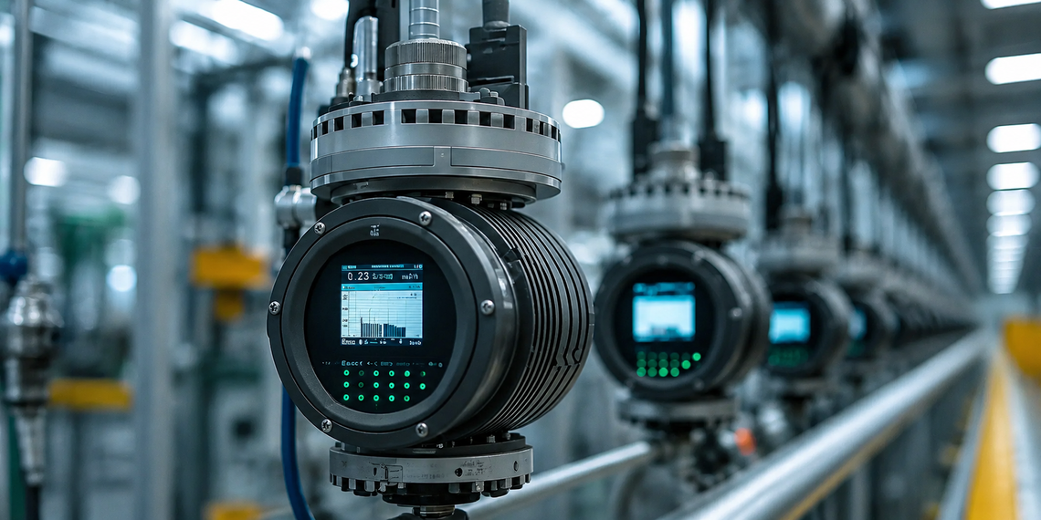
The Short Version
- Define the measurement before the sensor. What is being measured, over what range, to what uncertainty, how quickly, and what decision the reading feeds. A sensor is an answer, and it can only be specified once the question is written down.
- Accuracy and repeatability are different properties, and most control applications need repeatability. A sensor that consistently reads incorrectly can keep a process steady. A sensor that reads correctly on average but scatters cannot.
- Published accuracy is stated at reference conditions. What matters is the total error across your actual temperature range, pressure, and installation, which is usually a different and larger number.
- Output choice is an integration decision with consequences for noise immunity, diagnostics, and wiring. A current loop's live zero makes a broken wire look different from a genuine zero reading, which a voltage output does not do on its own.
- For each of the four families, the technology is chosen by what the sensor has to work against: target material for proximity, process medium and overpressure for pressure, response and immersion for temperature, and the material's own properties for level.
- Where the sensor is in a hazardous area or serves a safety function, that obligation attaches to the whole loop and the installation method, not to the sensor alone.
Sensor selection has an unusual failure mode. The equipment almost always works, in the sense that it produces a signal that moves when the process moves. What goes wrong is subtler: the reading drifts with ambient temperature, or it is repeatable but not accurate when someone finally checks it against a reference, or it responds too slowly to catch the event it was installed to catch, or it reads correctly in the pipe and incorrectly about the process because of where it was mounted.
None of those are defects. They are the consequence of specifying against a headline number rather than against a measurement requirement. This guide starts with the variables that apply to every industrial sensor, because getting those right carries over across all four families, then works through proximity, pressure, temperature, and level in turn to show how those same variables manifest differently in each. The four are not four separate problems so much as one problem with four sets of physics attached.
01. Start from the measurement, not the sensor
Eight questions define the measurement. Answer them before looking at any product.
- What physical quantity is being measured, and where exactly? The location matters as much as the quantity because the temperature at a pipe's wall differs from that at its center.
- What decision does the reading feed? Monitoring, closed-loop control, alarm, safety shutdown, and custody transfer place completely different demands on the same measurement.
- What is the operating range, and what is the full range, including startup, upset, and shutdown conditions, that the sensor must survive?
- What uncertainty is acceptable, expressed as a number rather than as a preference for accuracy?
- How fast must the measurement respond relative to how fast the process changes?
- What are the process conditions at the sensor: medium, temperature, pressure, flow, and anything abrasive, corrosive, coating, or crystallizing?
- What are the ambient conditions around the sensor, which are frequently harsher than the process conditions and are more often ignored?
- What has to happen when the sensor fails, and would you know that it had?
The last question separates a specification from a wish. A sensor that fails silently in a control loop can drive a process a long way before anyone notices, and whether the failure is detectable depends on the sensing technology, the output type, and the diagnostics available, all of which are specified.
02. The variables common to every sensor
Whatever is being measured, the same set of specification variables recurs. Working through them once means the four families later become questions of physics rather than of process.
- Measurand and range, including the required turndown. A sensor specified for a wide range may not resolve the narrow band you actually operate in.
- Uncertainty, expressed as a total error across operating conditions rather than a reference accuracy figure.
- Response time, and whether it is quoted as a time constant or as a time to reach a proportion of a step change. These are different definitions and are not comparable across datasheets without checking which is used.
- Output type and its integration requirements, covered in section 04.
- Power: supply voltage, whether the device is loop powered, and current draw.
- Process connection and wetted materials, where the sensor contacts the medium.
- Mounting arrangement and the clearances or immersion the technology requires to work as specified.
- Environmental protection against dust and water, temperature limits for the electronics, distinct from the process, vibration, and electromagnetic environment.
- Certification: hazardous area protection where required, functional safety where the sensor sits in a safety function, and calibration traceability.
- Service life and maintenance: what drifts, how often it needs calibration, and whether it can be verified or replaced without shutting the process down.
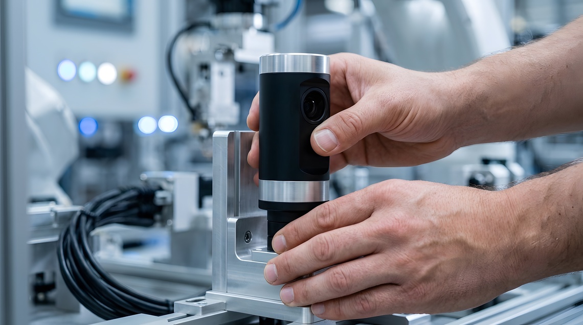
03. Accuracy, repeatability, and what error specifications actually mean
The distinction that decides most applications
Accuracy describes how close a reading is to the true value. Repeatability describes how consistently the sensor produces the same reading for the same condition. They are independent, and confusing them is the most common specification error in this category.
For closed-loop control, repeatability usually matters more. A sensor with a consistent offset holds a process at a stable point, and the setpoint was established using the same sensor. A sensor that is accurate on average but scatters between readings makes the loop hunt, and no amount of tuning fixes it.
That argument depends on four conditions, and it is worth checking them rather than assuming them. The offset has to be known, stable across the operating range rather than only at one point, stable over time between calibrations, and a property of the device rather than an artifact of its installation location. Where any of those fails, you do not have a stable offset; you have a drift you have not characterized yet.
Three classes of measurement then divide differently. Control measurements are usually dominated by repeatability under those conditions. Indicating, balancing, batching, quality, compliance, and custody measurements need installed accuracy and traceability directly, because the number is compared against something outside the loop. Protection and safety measurements are governed by neither headline figure; what matters is response time, failure mode, diagnostic coverage, and proof-test performance, and a device chosen on accuracy alone may be the wrong device entirely.
Reference conditions are not your conditions
Published accuracy is measured under defined reference conditions, typically at a specified ambient temperature, at a particular point in the range, and after calibration. Your installation differs on all three counts. The figures that describe real performance are the additional error terms: temperature effect over the operating range, the effect of static pressure where relevant, long-term drift between calibrations, and the effect of installation position.
Two sensors with identical headline accuracy can differ substantially once temperature effects and drift are accounted for, and the cheaper one is often less accurate there. Asking for a total error figure is the right instinct, but suppliers publish under several different names with different contents, so the number alone will not make three quotations comparable.
Ask instead for an uncertainty budget for your application, stating four things. What the supplier's figure includes, meaning which error terms are in it. What it excludes, particularly installation effects such as impulse lines, seals, mounting elevation, thermowell response and lead resistance, most of which sit outside their scope. The assumptions behind it cover ambient temperature, static pressure, range setting, orientation, fill fluid, wiring, and calibration interval. And what site data you have to supply for the remaining uncertainty to be calculated at all.
A supplier who can produce that is describing your measurement. One who cannot is describing their product, and the difference between the two figures is where the disappointment lives.
The other terms on the datasheet
- Linearity, which describes deviation from a straight line across the range, and matters where you use the whole span.
- Hysteresis, meaning a different reading depending on whether the measured value is rising or falling, which shows up as a deadband in control.
- Resolution is the smallest change the device can report and is not the same as accuracy, though it is frequently presented as such.
- Drift, quoted per unit time or per calibration interval, which determines how often the device needs attention.
Calibration
Establish what calibration is supplied, whether it is traceable, and what interval you intend to recalibrate on. Traceability to a national standard through an accredited laboratory is a documented chain rather than a claim, and where a measurement supports quality or regulatory obligations, the certificate matters as much as the device.
04. Output, power and integration
Discrete outputs
A discrete sensor reports a state rather than a value. The specification points are the switching logic, whether the output sources or sinks current, whether it is normally open or normally closed, the load it can switch, and how it behaves on power-up. The normally open or closed decision is as much a safety decision as a wiring one, because it determines what the system sees if a wire breaks.
Analog outputs
A current loop is the traditional industrial analog signal, and its advantages are structural. The signal is carried as current rather than voltage, so cable resistance does not change the value the receiver sees, provided the loop supply has sufficient compliance voltage to drive the current through the total loop resistance. That is the limit to check on a long run, and distance still affects noise pickup, grounding behavior, and any intrinsic safety calculation even when the value itself holds.
The signal also has a live zero, meaning the bottom of the range is a real current rather than nothing. A broken wire or a lost supply therefore produces a current below the valid range, which the control system can distinguish from a genuine zero reading if it has been configured to alarm on a zero reading. That is a specific and valuable diagnostic rather than a general one: it catches open circuits and certain wiring and power faults, and it does not detect a transmitter reading that is plausibly wrong. Many devices are also powered from the same two conductors that carry the signal.
A voltage output is simpler and common on short runs and on machine-mounted devices, but it is susceptible to voltage drop and to induced noise, and it has no equivalent of the live zero. Where a broken connection must be detectable, that is a reason to choose the current loop.
Digital outputs
Digital communication carries more than a value: device identification, diagnostics, multiple process variables, configuration and, on some protocols, parameter storage that lets a replacement device be configured automatically. Some protocols overlay digital communication onto an existing current loop, allowing configuration and diagnostics without sacrificing the analog signal. Others are point-to-point digital links intended for machine-level devices, and others again are full fieldbus networks.
Two practical points. Establish what your control system actually supports, including whether it can read the diagnostics rather than only the value, since diagnostics that nobody reads deliver nothing. And when devices are replaced by maintenance staff under time pressure, automatic parameter transfer to a replacement device is worth more than it looks on a datasheet.
Wiring, power and grounding
- Supply voltage and whether the device is loop-powered or separately powered, which affects both cabling and what happens during a power interruption.
- Cable type, screening and maximum length, and whether the manufacturer specifies a particular cable construction.
- Grounding and shield termination practices are a common cause of intermittent noise problems that get blamed on the sensor.
- Connector type or terminal arrangement, and whether it suits the environment and the space available at the mounting point.
05. Proximity sensing
What is being decided
A proximity sensor detects the presence of an object without contact. The technology is chosen almost entirely by what the target is made of and what surrounds it. The governing product standard is IEC 60947-5-2, published by the International Electrotechnical Commission, which covers inductive and capacitive proximity switches sensing metallic and non-metallic objects, ultrasonic switches sensing sound-reflecting objects, photoelectric switches, and non-mechanical magnetic switches.
The technologies and what each needs
- Inductive. Detects metal only, by the effect of the target on an electromagnetic field. Robust, unaffected by dust or most contamination, and the default for metal target detection. Sensing distance depends on the target metal, and a stated range assumes a defined standard target, so a smaller target or a different alloy reduces it.
- Capacitive. Detects most materials, including non-metals, and can sense through thin container walls, making it useful for detecting products inside packaging. More sensitive to humidity, condensation, and material buildup on the face, which can cause false detection.
- Photoelectric. Uses light, in through-beam, retroreflective, or diffuse arrangements. Through-beam offers the longest range and the most reliable detection because it does not depend on the target reflecting light back; diffuse is the simplest to install and depends on the target's color, finish, and angle. Dust, mist, and ambient light all affect performance.
- Ultrasonic. Detects sound-reflecting objects at longer range, largely independent of target color and transparency, which suits clear or shiny targets that defeat optical sensors. Affected by temperature, air movement, foam, and soft absorbent targets.
- Magnetic. Detects a magnet rather than the object, enabling sensing through non-ferrous walls, and is commonly used for cylinder positioning.
What the specification must carry
- Target material, size, shape and surface, since published sensing distance assumes a standard target of a defined material and dimension.
- The actual required sensing distance with margin, not the nominal figure. Effective sensing distance varies with temperature, supply voltage and unit-to-unit tolerance, and the assured operating distance is a smaller figure than the nominal one.
- Whether the sensor mounts flush in metal or must stand clear of surrounding material, since flush and non-flush versions of the same device have different sensing distances and different mounting rules.
- Required repeatability and switching frequency where the sensor detects fast-moving objects.
- Housing material, protection rating and resistance to whatever is present: coolant, weld spatter, washdown chemicals or abrasive dust.
06. Pressure sensing
What is being decided
The first decision is what the measurement is referenced to. Gauge pressure is measured relative to ambient atmospheric pressure and moves with the weather. Absolute pressure is referenced to vacuum and does not. Differential pressure measures the difference between two points and is the basis for flow measurement across a restriction and for level measurement in closed vessels. Choosing the wrong reference produces a measurement that is consistently wrong in a way that can be hard to spot.
What the specification must carry
- Range, and the pressure the device will actually operate at within it. A transmitter operating at the bottom of an oversized range yields poor resolution and a proportionally larger error, because error terms are often expressed relative to the span rather than to the reading.
- Overpressure and burst ratings against the worst case the installation can produce, including water hammer, pump deadhead, thermal expansion in a blocked line, and startup transients. The normal operating pressure is not the design case.
- Process connection and wetted materials, including the diaphragm, which is the part in contact with the medium and the part most likely to be attacked.
- Process temperature at the connection, and whether the medium must be cooled before reaching the sensor. Where the process is too hot, too viscous, corrosive, or prone to plugging, a diaphragm seal with a filled capillary isolates the device, at the cost of additional thermal effects and slower response.
- Ambient temperature at the electronics, which is a separate limit from the process temperature and is frequently the binding one.
- For differential pressure devices, the static pressure the device sits at affects the differential reading, and the correction is a specified error term.
- Required turndown, meaning how far the calibrated span can be reduced from the sensor's full range, and what that does to the error.
The errors that matter in service
Zero drift and temperature effect dominate real installations. A device that meets its accuracy specification at the reference temperature can introduce several times that error across a wide ambient temperature swing, which is why the total error figure under your conditions is the number to compare. Mounting position also introduces a zero offset on many devices, which is correctable at commissioning provided someone knows to do it.
The installation, which is where pressure measurement usually fails
More bad pressure measurements are caused by what sits between the process and the transmitter than by the transmitter. Settle these at specification, because each is a piping decision that becomes expensive to change.
- Impulse line routing and slope, so that the line self-drains or self-vents in the direction the application requires rather than trapping what it should not.
- Whether the line can plug, freeze or fill with condensate, and whether heat tracing or purging is required to prevent it.
- Condensate legs and wet legs, and whether the resulting standing head is being compensated in the calibration.
- Manifold and equalizing valve arrangement, which determines whether the device can be zeroed, isolated and removed without shutting the process down.
- Mounting elevation relative to the tapping point, which produces a fixed zero offset that has to be calibrated out rather than discovered.
- Where remote seals are used: capillary length and routing, fill fluid and its temperature limits, and the ambient gradient along the capillary, since all three affect both the reading and the response.
07. Temperature sensing
The sensing elements
- Thermocouples generate a small voltage from the junction of two dissimilar metals. They cover very wide temperature ranges, respond quickly, and are rugged and inexpensive. They are less accurate than resistance elements, require temperature compensation at the point where the signal leaves the thermocouple material, and drift over time. Types and their tolerances are defined in IEC 60584, published by the International Electrotechnical Commission, which specifies reference functions and tolerance classes, with ASTM E230 as the corresponding North American reference standard that distinguishes between standard and special limits of error.
- Resistance temperature detectors measure the change in electrical resistance of a metal, usually platinum, with temperature. They are more accurate, more stable and more repeatable than thermocouples over their range, and correspondingly more expensive with a narrower range. Tolerance classes are defined in IEC 60751, which sets out classes AA, A, B and C, each valid over a stated temperature range.
- Thermistors offer high sensitivity over a narrow range, which suits applications needing fine resolution near a single temperature.
- Infrared devices measure emitted radiation without contact, which suits moving, rotating or inaccessible targets. Accuracy depends on the emissivity of the target surface, which has to be known or determined, and on nothing obstructing the optical path.
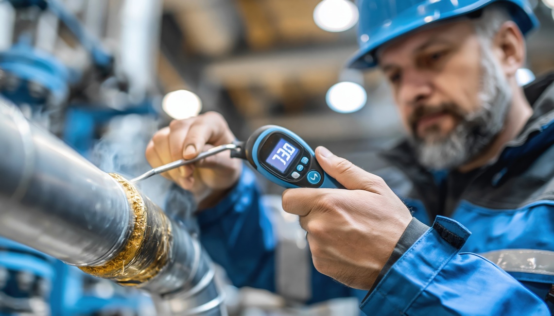
Wiring configuration for resistance elements
Because a resistance element is measured by the resistance across it, the lead wires' resistance is added to the measurement. A two-wire connection includes that lead resistance as an error. A three-wire arrangement compensates for most of it, and a four-wire arrangement effectively eliminates it. On long runs this is not a refinement, it is the difference between a usable measurement and a systematically wrong one, and it is a specification decision rather than an installation preference.
Thermowells, which are their own engineering problem
When the element cannot be exposed directly to the process, it sits in a thermowell: a closed tube that allows the sensor to be removed without breaching containment. Two consequences follow. Response slows, because heat must pass through the well and any air gap before reaching the element, and the fit between element and well matters. And the well is a bluff body inserted into a flowing stream, which sheds vortices that can excite it into resonance and break it off inside the pipe.
The mechanical design of thermowells is addressed in ASME PTC 19.3 TW, published by the American Society of Mechanical Engineers, commonly referred to as the wake frequency calculation. It applies to thermowells installed in pipes and process vessels and does not cover applications in process or industrial furnaces. The point buyers most often miss is where responsibility sits: the standard places the obligation to specify the process data used in the calculation, including temperature, velocity, density and pressure, on the designer of the system in which the thermowell is installed. That is you, not the supplier, and a calculation performed against assumed velocity is a calculation performed against an assumption.
The commercial arrangement can allocate who performs and reviews the calculation, and a capable supplier will often do both. What it does not move is the obligation to supply accurate process data, because nobody outside your plant can produce it.
Immersion and location
A temperature sensor reads its own temperature, not the process temperature, and the two converge only if enough of the sensor is immersed in the medium. Insufficient immersion allows heat to conduct along the stem to the ambient, pulling the reading toward ambient. Location matters equally: a sensor in a dead leg, downstream of a mixing point that has not yet finished mixing, or against a wall reads a value other than the bulk temperature. Specify the immersion depth and mounting location deliberately, because both are part of the measurement rather than the installation.
08. Level sensing
What is being decided
Level splits first into point measurement, which reports whether material is present at a specific height, and continuous measurement, which reports a level across a range. Point devices are simpler and are the usual choice for high and low alarms and pump control. Continuous devices are required where inventory, control, or reconciliation depends on knowing the actual level.
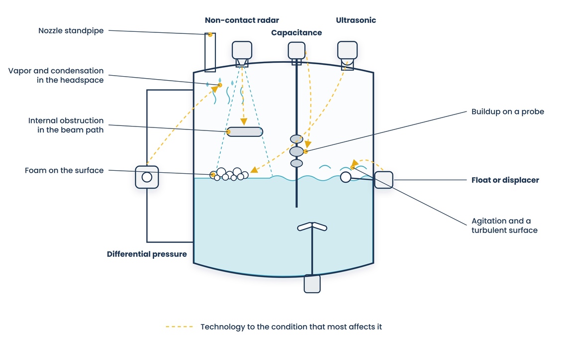
Technology is then chosen by the material's own properties, which is what makes level the most application-specific of the four families.
The technologies and what defeats each
- Radar, in guided and non-contact forms, measures the time for a signal to reach the surface and return. It tolerates temperature and pressure variation far better than ultrasonic does, which is its main advantage, though it is not immune: vapor composition, condensation on the antenna, buildup on the probe and false reflections from internal fittings all degrade it. Performance depends most on how reflective the material is to the signal, so low-reflectivity materials are harder, and guided versions using a probe handle those better than non-contact versions at the cost of contact with the medium.
- Ultrasonic measurements measure the time for a sound pulse to return, making them sensitive to anything that affects sound in the vapor space: temperature gradients, pressure, vapor, foam, and dust. It cannot be used in vacuum.
- Hydrostatic pressure determines level from the pressure exerted by a column of liquid, which requires the liquid's density to be known and constant. A density change produces a level error with no indication that anything is wrong.
- Differential pressure measures across the vessel to compensate for pressure above the liquid, which is the traditional approach in closed and pressurized vessels, and which brings its own installation requirements for the impulse lines.
- Capacitance depends on the electrical properties of the material between the probe and the vessel wall and is affected by material buildup on the probe and by changes in the material's properties.
- Vibrating fork and similar point devices detect the damping of a vibrating element when material covers it and are largely indifferent to material properties, which is why they are commonly used as independent high-level alarms.
- Float and displacer devices are mechanical, simple, and well understood, with moving parts that can stick in service.
Overfill and safety
Where a level measurement forms part of an overfill prevention or safety function, the requirement extends beyond the sensor to the whole loop and to its testing regime. An independent point device on a different technology from the continuous measurement is a common arrangement precisely because it fails differently. Where a safety integrity requirement applies, it applies to the function rather than the device, and the device's suitability for that function must be documented rather than assumed.
09. Environment, certification, and what to send a supplier
Ingress protection and enclosure
Ingress protection ratings against solids and liquids are defined in IEC 60529, published by the International Electrotechnical Commission, with the first digit rating protection against solids and the second against liquids. High-pressure and high-temperature washdown is covered by a separate ISO standard rather than IEC 60529, so a supplier citing it is referring to a different document. Ratings apply to specific product variants and to the complete assembly including connectors and cable entries, so a rated device with an unrated connector is not a rated installation.
Hazardous areas
Where a flammable atmosphere may be present, the sensor, its wiring method and its installation all fall within the area classification. Different protection concepts achieve safety by different means: limiting the energy available in the circuit, containing an ignition within an enclosure, or preventing the atmosphere from reaching the ignition source. Which concepts are acceptable depends on the classification of the specific location, and North American and international frameworks describe areas differently, so a device certified under one is not automatically acceptable under the other.
Two practical points. Energy-limited installations impose requirements on the entire loop, including barriers, cable parameters, and grounding, so certification is a property of the installed system rather than of the device in isolation. And area classification is determined by a competent person for the specific site, not inferred from what is stored nearby.
Functional safety
Where a sensor forms part of a safety instrumented function, its suitability has to be documented, the whole function has to be assessed rather than the device alone, and proof test requirements and intervals form part of the design. A device described as suitable for use in a safety function is making a narrower claim than it appears to, and the claim needs to be read rather than accepted.
Common specification errors and what they cost
- Specifying accuracy where the application needs repeatability. Buys a number that does not help the loop.
- Comparing reference accuracy figures between devices. Hides the temperature effect and drift where the real difference usually sits.
- Sizing a range around the maximum rather than the operating point. Produces poor resolution and larger error exactly where you measure.
- Taking a proximity sensing distance from the datasheet without checking the target material and size against the standard target it assumes.
- Overlooking overpressure cases such as water hammer, deadhead, and thermal expansion in a blocked line.
- Using a two-wire connection for a resistance element on a long run, which builds a systematic error into the measurement.
- Specifying a thermowell without supplying real process velocity, when the standard places that responsibility on the system designer.
- Treating hazardous area certification as a device property rather than a property of the installed loop.
What to send a supplier
- A description of the measurement: what, where, over what range, to what uncertainty, and how fast.
- What the reading is used for, including whether it feeds into control, alarm, or safety functions.
- Full process conditions at the sensor, including upset and startup cases, not just normal operation.
- Ambient conditions at the device, including temperature range, washdown, vibration and electromagnetic environment.
- A drawing or photograph of the intended mounting location, with available clearances, immersion depth, straight run and access for maintenance.
- For proximity: target material, size, shape, surface and speed, and whether flush mounting is required.
- For pressure: reference type, worst-case overpressure, wetted-material constraints, and whether the process requires isolation.
- For temperature: required response, immersion depth available, whether a thermowell is required, and the process velocity, density, pressure and temperature needed for its calculation.
- For level: vessel drawing, material properties, and an honest description of foam, agitation, coating, vapor, and obstructions.
- Control system and required output type, including whether diagnostics will be read.
- Certification requirements: area classification, functional safety requirement, and calibration traceability.
- Maintenance expectations: calibration interval, whether the device must be removable in service, and spares strategy.
Lifecycle
Four factors determine whether the measurement will remain trustworthy in five years, and all four are cheaper to specify than to retrofit.
- Calibration access: whether the device can be verified in place or must be removed, and whether removal requires shutting down or isolating the process.
- Records: whether as-found and as-left values are required at each calibration, and in what format they have to be delivered.
- Standardization: whether this device will be a one-off or part of a family you hold spares for, since a plant carrying six variants of the same measurement carries six sets of spares and six sets of knowledge.
- Replacement: whether configuration is backed up and can be restored to a new device, and whether a replacement can be installed and returned to service without re-engineering the loop.
Take This to Your Next Conversation
Fifteen questions drawn from this guide. The answers together will tell you whether a supplier has specified for your measurement or quoted their standard device.
- What total error should I expect across my actual temperature range and operating conditions, rather than at reference conditions?
- How much of that error is temperature effect, and how much is drift between calibrations?
- Is this device better in terms of accuracy or repeatability, and which does my application actually need?
- Where in its range will this device be operating, and what does that do to resolution and error?
- How does this device fail, and would my control system know that it had?
- What does the installation have to provide for this device to meet its specification: clearance, immersion, straight run or beam path?
- For proximity: what standard target is the sensing distance based on, and what does my actual target give?
- For pressure: what is the overpressure rating, and have you seen my worst-case transient?
- For temperature: does this need a thermowell, and what process velocity did you use in the calculation?
- For level: which of my process conditions, foam, agitation, buildup or vapor, is this technology most vulnerable to?
- What calibration ships with it, is it traceable, and what interval do you recommend?
- Which certification applies to my area classification, and what must the installation do to maintain it?
- What information would make you refuse to guarantee this measurement, and what installation changes would remove that risk?
- Can you provide an uncertainty budget for my application, showing what your figure includes, what it excludes, and what site data you need from me to complete it?
- If this measurement feeds a protection function rather than a control loop, what are the response time, failure mode, and diagnostic coverage?
About this guide
Written by the Industrial Web Search editorial team. This guidance is general and does not replace engineering advice for a specific measurement or installation. The standards referenced here are revised periodically and their current editions are the authority. Hazardous area classification, functional safety requirements and calibration obligations vary by jurisdiction, by industry, and by site, and area classification must be determined by a competent person for the specific location. Verify every specification against the current edition of the governing standard and against manufacturer documentation for the specific device, and confirm certification and safety requirements with a qualified engineer for your installation.